


30
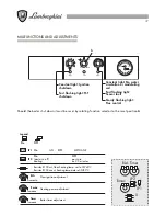
ELECTRICAL CONNECTIONS - WIRING DIAGRAMS
The boiler must be connected to an earthed, single-phase 230V - 50 Hz mains supply by means of a
three-wire cable, ensuring that connections to the LINE and NEUTRAL terminals are made correctly.
A bipolar switch must be used with contacts opening to at least 3 mm.
The power lead must only be replaced by another with the following characteristics: “HAR H05 vv-F” 3
x 1.00 mm
2
.
(You are strongly advised to use original LAMBORGHINI accessories and spare parts
only).
Installation must be made in compliance with safety REGULATIONS IN FORCE.
Make a good earth connection.
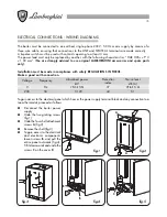
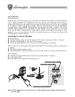
To gain access to the electrical panel which houses the power supply terminal block and any connection to a
room thermostat, proceed as follows:
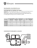
Voltage
V
230
Frequency
Absorbed power
kW
Hz
Noise level
dB (A)
●
Disconnect the boiler power
supply
●
Undo the two grating screws
(fig.1)
●
Undo the four shell attachment
screws
A
(fig.2)
●
Remove the shell (fig.3)
●
To gain access to the electrical
and electronic components
loosen screws
B
and pull the
entire panel outwards (fig.4).
Tilt it downwards and undo the
screws
C
on the cover
D
fig.3
fig.4
50
fig.1
fig.2
fig.5
VELA X N 24
51
Protection
index
IP
44
VELA X N 24
0,120
D
C
B
B
A
A


