


69
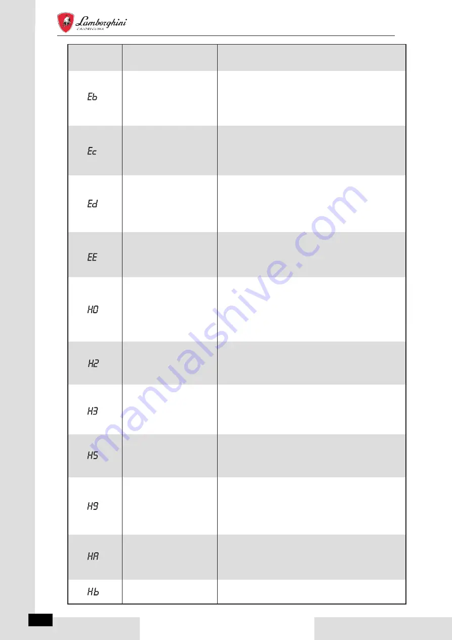
ERROR
CODE
MALFUNCTION
OR PROTECTION
FAILURE CAUSE
AND CORRECTIVE ACTION
1. The EEprom parameter is error, rewrite the EEprom data.
2. EEprom chip part is broken, change a new EEprom chip
part.
3. Main control board of hydraulic module is broken, change a
new PCB.
Hydraulic module EEprom
failure
1.Wire doesn’t connect between main control board PCB B and
main control board of hydraulic module. connect the wire.
2.Communication wire sequence is not right. Reconnect the
wire in the right sequence.
3. Check whether there is a high magnetic field or high power
interfere, such as lifts, large power transformers, etc.. To add a
barrier to protect the unit or to move the unit to the other place.
Communication fault between
main board PCB B and main
Control board of hydraulic
module
1.Check the resistance of the sensor
2.The Tw_in sensor connector is loosen. Reconnect it.
3.The Tw_in sensor connector is wet or there is water in.
remove the water, make the connector dry. Add waterproof
adhesive
4.The Tw_in sensor failure, change a new sensor.
Inlet water temp.sensor
(Tw_in) malfunction
1.Check the resistance of the sensor.
2. The Tw2 sensor connector is loosen. Reconnect it.
3.The Tw2 sensor connector is wet or there is water in.
Remove the water, make the connector dry. add waterproof
adhesive.
4. The Tw2 sensor failure, change a new sensor.
Outlet water for zone 2
temp.sensor (Tw2) fault
1. The TW_out sensor connector is loosen. Reconnect it.
2.The TW_out sensor connector is wet or there is water in.
remove the water, make the connector dry. add waterproof
adhesive.
3. The TW_out sensor failure, change a new sensor.
Outlet water
temp.sensor(Tw_out)
fault
1.Check the resistance of the sensor.
2. The Ta senor is in the interface.
3. The Ta sensor failure
,
change a new sensor or change a
new interface, or reset the Ta, connect a new Ta from the
hydraulic module PCB.
Room temp.sensor(Ta) fault
1.Check the resistance of the sensor
2.The T2 sensor connector is loosen. Reconnect it.
3.The T2 sensor connector is wet or there is water in. remove
the water, make the connector dry. Add waterproof adhesive
4. The T2 sensor failure, change a new sensor.
Refrigerant liquid
temp.sensor(T2) fault
1.Check the resistance of the sensor.
2.The T2B sensor connector is loosen. Reconnect it.
3.The T2B sensor connector is wet or there is water in. remove
the water, make the connector dry. Add waterproof adhesive
4. The T2B sensor failure, change a new sensor.
Refrigerant gas
temp.sensor(T2B) fault
Three times “PP”
protection and
Tw_out
<
7
℃
The same to "PP".
Solar
temp.sensor(Tsolar) fault
1. Check the resistance of the sensor.
2. The Tsolar sensor connector is loosen, reconnect it.
3. The Tsolar sensor connector is wet or there is water in,
remove the water ,make the connector dry.Add waterproof
adhesive.
4. The Tsolar sensor failure,change a new sensor.
Buffer tank low
temp.sensor(Tbt2) fault
1.Check the resistance of the sensor.
2.The Tbt2 sensor connector is loosen,reconnect it.
3.The Tbt2 sensor connector is wet or there is water in,remove
the water ,make the connector dry.Add waterproof adhesive.
4.The Tbt2 sensor failure,change a new sensor."
EN
IDOLA M 3.2
04÷16T
CAUTION
34
Ethylene Glycol and Propylene Glycol are TOXIC
WARNING
NOTE
During filling, it might not be possible to remove all air in the system. Remaining air will be removed through the
automatic air purge valves during the first operating hours of the system. Topping up the water afterwards might be
required.
The water pressure will vary depending on the water temperature (higher pressure at higher water temperature).
However, at all times water pressure should remain above 0.3 bar to avoid air entering the circuit.
The unit might drain-off too much water through the pressure relief valve.
Water quality should be complied with EN 98/83 EC Directives.
Detailed water quality condition can be found in EN 98/83 EC Directives.
Connect the water supply to the filling valve and open the valve.
Make sure the automatic air purge valve is open (at least 2 turns).
Fill with water pressure of approximately 2.0 bar. Remove air in the circuit as much as possible using the air purge
valves. Air in the water circuit could lead to malfunction of the backup electric heater.
9.5 Filling water
Do not fasten the black plastic cover on
the vent valve at the topside of the unit
when the system is running. Open air
purge valve, turn anticlockWise at least
2 full turns to release air from the
system.
CounterclockWise rotation, remove the flow switch.
Drying the flow switch completely.
When the unit is not running for a long time, make sure the unit is powered on all the time. If you want to cut off the
power, the water in the system pipe needs to be drained clean to avoid the unit and pipeline system being damaged by
freezing. Also the power of the unit needs to be cut off after water in the system is drained off.
Cod. 3QE47850 - Rev. 00 - 03/2022