1. Connect the load in series with the shunt to the output terminals.
2. Plug in a jumpered plug for normal operation, see paragraph 3.3.
3. Connect the multimeter across the shunt.
4. Turn on the supply and adjust the output current for 80MV across the shunt.
5. Connect the multimeter between TP5 and TP15 and adjust R166 for a meter
reading of 4.00 volts.
6. Adjust R121 for a front panel meter reading of 40 Amps.
7. Turn off the supply and adjust the current control maximum CCW.
5.3.2 VOLTMETER
1. Repeat steps 1 and 2 as in paragraph 5.3.1.
2. Connect the voltmeter across the output terminals.
3. Turn on the supply and adjust the output for approximately 125Vdc.
4. Adjust R145 for a front panel meter reading of 125Vdc.
5.3.3 FULL SCALE CURRENT OUTPUT
1. Repeat steps 1, 2 and 3 as in paragraph 5.3.1.
2. Turn on the front panel current control full CCW.
3. The output current should be zero, if not, adjust R160 for zero current output.
4. Adjust the current control maximum CW.
5. Adjust R179 for the desired maximum current output. (40 Amps).
5.3.4 AUXILIARY CALIBRATION
This portion of the procedure normally does not need to be performed, unless
Paragraphs 5.3.1, 5.3.2 and 5.3.3 can not be performed.
1 mA Current Source Calibration:
1. Connect a current meter between Pins 8 and 11 of P1.
2. Adjust R137 for 1mA.
Program Limit:
1. Connect a voltmeter between TP107 and TP113.
2. Adjust R127 for a voltmeter reading of 5.1 volts.
Min. IO Detector:
1. Connect the voltmeter between E2-2 and E2-1.
2. Adjust the output current for 0 to 10 Amps. The voltmeter should switch from
13 volt to less than .6V at approximately 4 Amps.
Page 16 of 18
83-475-001 Rev. D
Summary of Contents for ESKI
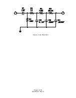
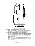
Page 6: ...Figure 1 Loss Pass Filter Page 4 of 18 83 475 001 Rev D...
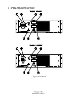
Page 8: ...3 OPERATING INSTRUCTIONS Figure 2 Front Panels Page 6 of 18 83 475 001 Rev D...
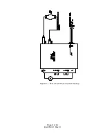
Page 11: ...Figure 3 1 Phase Front Panel Control Hookup Page 9 of 18 83 475 001 Rev D...
Page 14: ...Figure 4A 1 Phase External Control Hookup Page 12 of 18 83 475 001 Rev D...

