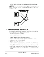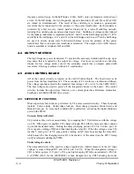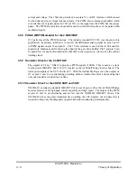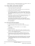
3.10 REMOTE TURN ON
EXTERNAL VOLTAGE SOURCE: Connect either an external 12-24 Vdc voltage supply
or a 24-115 Vac voltage supply to pins TB1/J1-15 & 16. The link between Terminals 16 &
17 must be removed. NOTE: Terminals are polarity sensitive DC. Terminal 15 is positive
and terminal 16 is negative.
DRY CONTACT: Connect a N/O voltage switch or contactor between terminal 16 & 17 of
TB1/J1. Open contact implies Power supply is disabled and close contact enable the power
supply.
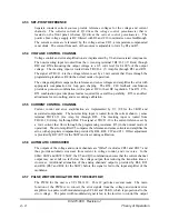
3.11 LOAD CONNECTION
Each load must be connected to the power supply output terminals using separate pairs of
connecting wires. This will minimize mutual coupling effects between loads and will retain
full advantage of the low output impedance of the power supply. Each pair of connecting
wires must be as short as possible and twisted or shielded if strong AC or RF fields are
present to reduce noise pickup. Either positive or negative voltages can be applied to the
load by grounding one of the output terminals to chassis. The system should not be grounded
at more than one point. Connections between the load and power supply should be very tight
especially on units rated for high output current. The wires to the load should be as short as
possible and heavy enough to carry the maximum output current of the supply. The
following table may be helpful in determining the proper wire size.
20
LESS
8
45
18
6
6
60
16
10
4
80
14
15
0
120
12
20
2/0
150
10
30
4/0
200
RECOMMENDED COPPER
WIRE SIZE
CURRENT
(Amps)
RECOMMENDED COPPER
WIRE SIZE
CURRENT
(Amps)
Table 3.3 Recommended Wire Size for Load Connection
83-473-000 Revision J
3 - 14
Operating Instructions


