unit drifts upward, it will become current limited rather than carry an excessive share of
load current.
IMPORTANT:
In order to run power supplies with OVP in parallel, modifications must
be made. Please contact the factory for further instructions, before connecting supplies
with OVP in parallel.
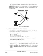
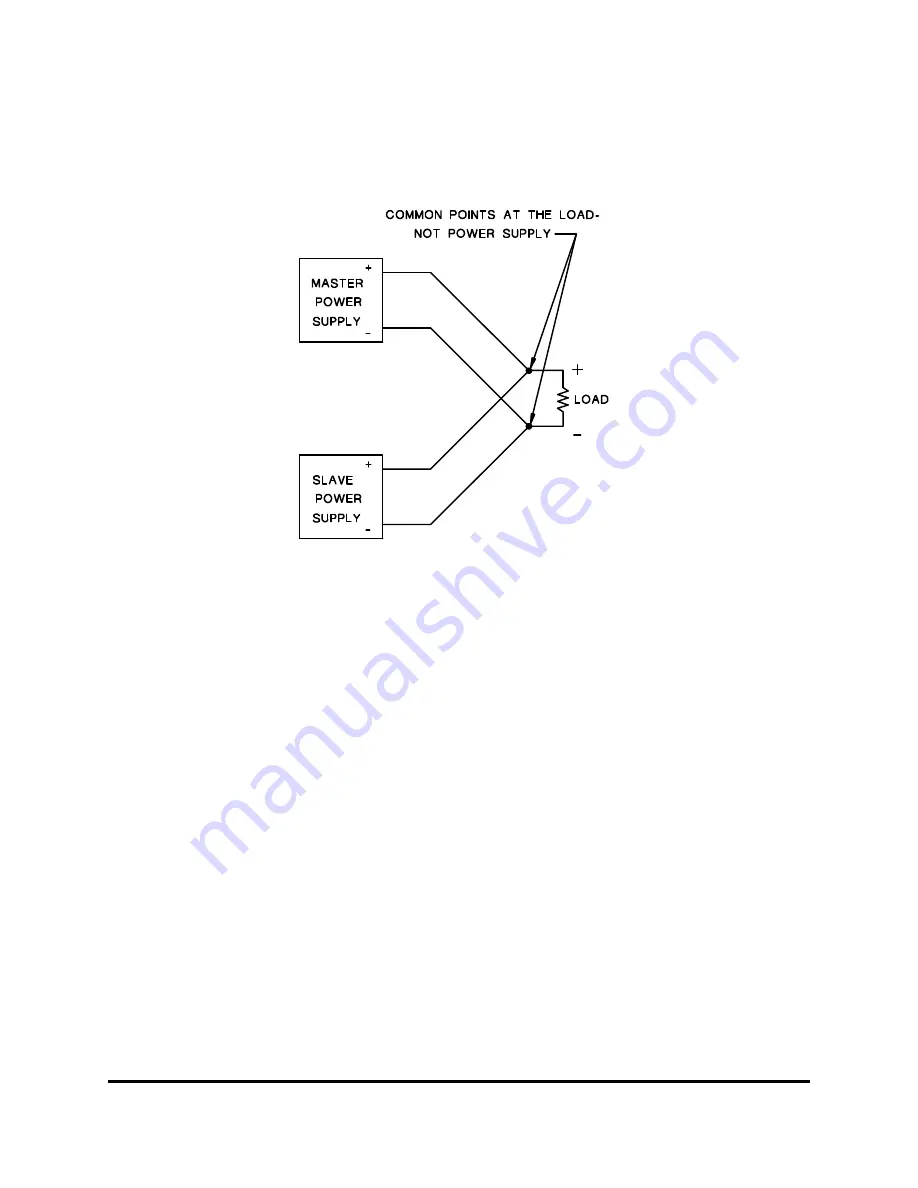
Figure 3.11: Parallel Operation
3.5 PARALLEL OPERATION - MASTER/SLAVE
In this configuration, the power supply designated the master is used to control the voltage
and current operation of all other supplies, referred to as slaves.
1. Disconnect the following links of all slaves:
TB1/J1-13, TB1/J1-14
TB1/J1-9, TB1/J1-10 & TB1/J1-11
2. Connect a link between TB1/J1-10 and TB1/J1-12 of all slaves.
3. Connect a wire between the master supply TB1/J1-12 and TB1/J1-13 of each slave.
4. Rotate Current control of slave fully clockwise.
5. Turn each slave on and then the master.
6. Adjust the master for required output voltage or current. The output leads from each
power supply must be of equal resistance (wire gauge and length) to ensure equal
sharing. Refer to Figure 3.11.
7. In case of noise problems, add a 1µF capacitor between TB1/J1-13 & 14 of Slave and
replace the jumper between TB1/J1-13 of Slave and TB1/J1-12 of Master with a 4.7k
Ω
resistor.
83-473-000 Revision J
3 - 10
Operating Instructions

