


O & M Manual – Insulated Case ATS Rev: October 2020
Publication Number:
MN0100700E
Version: V10.01.20
Page 14
6.
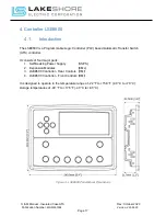
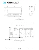
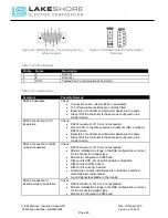
Control Wire:
Connect the "Engine Start" wires to terminals designated on the specific
units schematic drawing "XXXXXX-03" drawings. (Typical: "028" and "029". Utility to
Generator Configuration. See Figure 2 – Typical Control Wire
This number is subject to change. Please see unit drawings for specifics on current ATS.)
[Also NOTE that if this is a Generator to Generator configuration, there will be two sets of
“Engine Start” contacts. If the ATS is a Utility to Utility, there will be no “Engine Start”
contacts. Please see unit drawings for specifics on current ATS.]
LUG RANGE NOTE: Please refer to the outline drawing "XXXXXX-02" of the specific ATS
for lug ranges for Utility, Generator and Load connections for the Power Cables.
CURRENT TRANSFORMER (CT) NOTE: Please refer to the schematic drawing
"XXXXXX-03" to see if the present unit requires that monitoring CT’s be included with the
power cable connections and install them according to the drawing. Verify the CT’s proper
orientation to the current flow of the system.
7.
Power Cables:
Connect the cables from Utility to the Normal Breaker "NS". When
installing the power cables, be careful not to disturb or damage the control wires that go
to the various terminals.
3
φ
Systems: Terminals are labeled NL1, NL2, NL3, NE and GND. (Wye)
3
φ
Systems: Terminals are labeled NL1, NL2, NL3 and GND.
(Delta)
1
φ
Systems: Terminals are labeled NL1, NL2, NE and GND.
(Polyphase)
1
φ
Systems: Terminals are labeled NL1, NE and GND.
(Single Phase)
8.
Power Cables:
Connect the cables from Back Up Power Supply or Generator to the
Emergency Breaker "ES". When installing the power cables, be careful not to disturb or
damage the control wires that go to the various terminals.
3
φ
Systems: Terminals are labeled EL1, EL2, EL3, NE and GND. (Wye)
3
φ
Systems: Terminals are labeled EL1, EL2, EL3 and GND.
(Delta)
1
φ
Systems: Terminals are labeled EL1, EL2, NE and GND.
(Polyphase)
1
φ
Systems: Terminals are labeled EL1, NE and GND.
(Single Phase)
9.
Power Cables:
Connect the cables from the Load to the load lugs on the ATS. When
installing the power cables, be careful not to disturb or damage the control wires that go
to the various terminals.
3
φ
Systems: Terminals are labeled L1, L2, L3, NE and GND.
(Wye)
3
φ
Systems: Terminals are labeled L1, L2, L3 and GND.
(Delta)
1
φ
Systems: Terminals are labeled L1, L2, NE and GND.
(Polyphase)
1
φ
Systems: Terminals are labeled L1, NE and GND.
(Single Phase)
10.
Power Cables:
Verify that the phase sequence rotation of the normal and emergency
sources match and are connected to the same load connection via their respective molded
case unit.
Important Note:
Failure to do this will result in damage to the transfer switch/other
equipment and will void the warranty extended by Lake Shore Electric.
11.
Power Cables:
A ground lug is provided on all transfer switches. This lug must be
connected to earth ground.
Caution:
Be sure to check that all power cable lugs are torqued to the applicable
requirement for the switch (see Appendix B).


