120
CHAPTER 5:
Advanced Operation
Model CRX-6.5K Probe Station
5.3.6.3 Adjusting the Fit of Microwave Cables
An appropriately fitted cable will tighten to the probe connector while the probe arm
touches flush or is less than 2 mm from the probe mount. However, there are two sit-
uations for which you may need to make adjustments of your semirigid high fre-
quency cables. First, if the connector plug does not smoothly tighten to the probe
socket, you will need to make an adjustment. If there is too much tension or misalign-
ment in mating the semirigid cable to the connector, the high frequency connectors
may be damaged. Second, if you are able to tighten the connector plug to the probe
socket, but there is more than a 2 mm gap between the probe arm and the probe
body, then you will need to make an adjustment.
A few adjustments can be made to change the relative positions of the cables and the
probes. These are listed in order of increasing difficulty. The more difficult methods
allow for more adjustment range.
First Method: Rotate the Cable Feedthrough Assembly
1. Remove the micro-manipulated stage following the steps in section 5.3.2.
2.
Optional:
Remove the bellows following steps 1 to 2 in section 5.3.3.
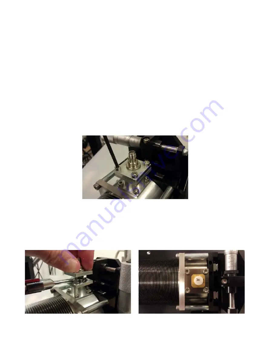
3. Remove the top set of four M3 screws holding the cable feedthrough to the
feedthrough tower (FIGURE 5-20).
4. Gently pull up on the feedthrough, and using an 8 mm torque wrench, loosen the
connection of the semirigid cable to the feedthrough so that the feedthrough
may be rotated.
5. Rotate the feedthrough assembly into position and re-tighten the connection.
The cable does not pass through the center of the feedthrough assembly
(FIGURE 5-21). Rotating this assembly changes the position of the cable end that
attaches to the probe.
6. Start but do not tighten all four feedthrough assembly screws.
FIGURE 5-20
Remove the top set of four M3 screws
FIGURE 5-21
Left: Rotate the feedthrough assembly into position and re-tighten the connection;
Right: The off-centered position on the cable feedthrough assembly


