https://www.lairdconnect.com/vela-if820-series
15
© Copyright 2023 Laird Connectivity. All Rights
Reserved
https://www.lairdconnect.com/contact
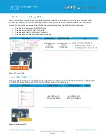
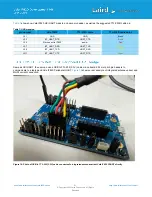
One tri-color LED is reserved for user programming with the Vela IF820. It connects to one of the pins of the Vela IF820
module pins, mapping to P4 of the CYW20820 chipset. Please see the GPIO pin in different variants in the table below.
Another tri-color LED is connected to the RP2040 to provide user feedback. The RP2040 LED functions are:
•
Flashes white twice when the RP2040 boots
•
Flashes blue for UART0 (HCI) TX and RX
•
Flashes red for UART1 (EZ-Serial) TX and RX
•
Flashes green for USB DAP (debugger) commands
Schematic
MHF4 variant
Antenna variant
note
Vela IF820 pin 5
(P4 of
CYW20820)
Vela IF820 pin 37
(P4 of
CYW20820)
Jumper should be installed in:
▪
MHF4 variant : J1 pin 7
– 8
▪
Antenna variant : J2 pin 17 - 18
Figure 9: Tri-color LED
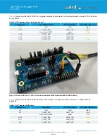
One color LED reserved for user applications with Vela IF820. It connects to one of Vela IF820 module pins, mapping to P27
of CYW20820 chipset. Please see the GPIO pin in different variant in the table below.
Schematic
MHF4 variant
Antenna variant
note
Vela IF820 pin 23
(P27 of CYW20820)
Vela IF820 pin 33
(P27 of CYW20820)
Figure 10: One color LED
Tri-color LED
one color LED
Summary of Contents for Vela IF820
Page 1: ...Version 1 0...


