https://www.lairdconnect.com/vela-if820-series
9
© Copyright 2023 Laird Connectivity. All Rights
Reserved
https://www.lairdconnect.com/contact
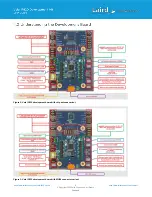
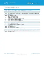
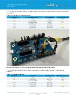
Table 2: Configuration switches and jumpers
Connector Descriptions
J1,J2,J3
1” dual row header pins for connecting the Vela IF820 IO pins to on DVK peripherals
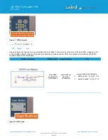
SW1
Button for user interaction with Vela IF820
SW2
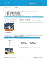
Recovery button, used in combination with the reset button to ensure user can program the Vela IF820 over
the HCI UART.
SW301
Reset button for Vela IF820
J6
for user control the power source
J6 with jumper -- USB 5V source
J6 open -- user can use external source connect to J6
J9
Current measurement header for Vela IF820
J4
Current measurement header for Vela IF820 VBAT
J5
Current measurement header for Vela IF820 VDDIO
J8
Header exposing RP2040 VDDIO
J7
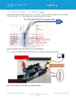
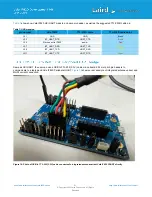
TAG connector (TC2030) for programming the RP2040
Default not fitted
SW4
Reset button for RP2040
SW3
For firmware programming to RP2040
P202
Qwiic connector connected with Vela IF820 for I
2
C interface
J201, J202
mikroBUS connector provides SPI, I
2
C, HCI UART, GPIO, Reset interface connected with Vela IF820
P900
Micro USB connector
Summary of Contents for Vela IF820
Page 1: ...Version 1 0...


