Laird RAMP User Manual Download Page 6

RAMP DVK Guide 

Version 4.0 


Americas: +1-800-492-2320 Option 3  

Laird Technologies 

Europe: +44-1628-858-940  

Hong Kong: +852 2923 0610 

www.lairdtech.com/ramp
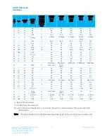
 

Switch 

Definition 

WR ENABLE (S2) 

When this pushbutton is pressed, it takes the Write Enable pin (AC4424, 

AC5124, AC3124, AC1524) or G11 pin (AC4490, AC4486, AC4790, AC4868) 

Low. This button must be pressed and held during the write process for 

AC5124, AC3124, AC1524, and AC4424 product families. 

RS485 or TTL Radio 

If using a transceiver module fitted with a RS-485 interface chip, RS485 Radio 

should be selected. This converts the transceiver’s RS-485 interface to serial, 
which is then converted to the interface selected by the COMM SELECT 

jumper.  
 

If not using a transceiver module fitted with a RS-485 interface chip, TTL Radio 
should be selected. 

COMM SELECT (J12) 

When this jumper is moved to the 

RS232 Enable position, RS-232 

communication is enabled through the DB9 connector (J2). 

 
When this jumper is moved to the 

RS485 Enable position, RS-485 

communication is enabled through the RS-485 header pins. 
 

When this jumper is moved to the 

Loopback Mode position, the transceiver 

TxD pin is tied to the transceiver RxD pin. This is only valid for AC5124, 

AC4424, AC4486, AC4490, AC4790, AC4868 products. RST mode must be 
disabled on the transceiver when Loopback Mode is enabled. This mode is not 

compatible with RS485 Radio selection. 

RADIO VOLTAGE (J9) 

When this jumper is moved to the 

+5V Radio position, the transceiver is 

powered with 5 volts. 
 

When this jumper is moved to the 

+3.3V Radio position, the transceiver is 

powered with 3.3 volts. The AC4x90-1000, AC4868, and AC4x90-1x1 must 

have this jumper set to 3.3 volts. 
 

Special care should be taken when setting this jumper. An improper setting 
can cause catastrophic damage to the transceiver.


FORCED 
CONFIGURATION (J11) 

When this jumper is moved to the 

Normal Operation position, the transceiver 

communicates at the baud rate configured in the EEPROM. 

 
When the jumper is moved to the 

Forced 9600 Recovery position, the 

transceiver interface baud rate is forced to 9600 baud upon reset. This is for 
EEPROM recovery only and should not be used in normal operation. 

POWER SOURCE (J7) 

When this jumper is moved to the 

Power Conn position, power is supplied to 

the SDK board through the power connector (J4). 

 
When this jumper is moved to the 

Batteries position, power is supplied to the 

SDK board through the two AA battery sockets on the bottom of the SDK 
board. 


Special care should be taken when selecting batteries to power the SDK. High 

quality alkaline batteries should be used. Do not mix battery types or batteries 
that have been used unequally as performance could suffer. Four alkaline 

batteries produce a voltage of six volts. A minimum of 5.5 volts is required to 
power the SDK board. Power should be constantly monitored when using 

Summary of Contents for RAMP

Page 1: ...RAMP Development Kit User s Guide Version 4 0 wireless support lairdtech com www lairdtech com wireless ...

Page 2: ...RAMP DVK Guide Version 4 0 Americas 1 800 492 2320 Option 3 2 Laird Technologies Europe 44 1628 858 940 Hong Kong 852 2923 0610 www lairdtech com ramp REVISION HISTORY Version Date Changes ...

Page 3: ...Contents Revision History 2 Contents 3 Overview 4 Hardware 4 SDK Board 4 Interfacing the SDK Board to Other RS 232 Hardware 9 Interfacing the SDK Board to RS 485 Equipment 9 Power Requirements 9 Software 10 USB Software Installation 10 SDK Software Installation 10 PC Settings 11 Configure 12 Terminal Chat 14 Range Test 15 Command 16 Troubleshooting 18 ...

Page 4: ...SDK includes the following SDK interface boards 2 AC power adapters 2 DB9 to DB9 cables 2 USB cables 2 Omni directional dipole antennas with a 5 pigtail and MMCX connector 2 Other antennas are available for testing Card with software utilities and documentation download information HARDWARE SDK Board The SDK board is provided so the developer can use a standard PC interface to operate the transcei...

Page 5: ... Reflects the state of the Command Data pin AC4490 AC4486 AC4424 AC4790 AC4868 the TE pin AC3124 AC1524 and the Pktmode pin AC5124 This is controlled by the PC RTS pin when the Program Mode Normal Mode switch is set to Program Mode Lights when this pin goes Low Table 2 LEDs AC4490 only section includes AC4486 AC4790 and AC4868 LED Definition Potentiometer AD In This varies the voltage 0 3 3 V pres...

Page 6: ...abled This mode is not compatible with RS485 Radio selection RADIO VOLTAGE J9 When this jumper is moved to the 5V Radio position the transceiver is powered with 5 volts When this jumper is moved to the 3 3V Radio position the transceiver is powered with 3 3 volts The AC4x90 1000 AC4868 and AC4x90 1x1 must have this jumper set to 3 3 volts Special care should be taken when setting this jumper An im...

Page 7: ...al definitions J2 Pin J1 Pin Signal Name Description Direction 1 36 DCD Data Carrier Detect I 2 14 RXD Receive Data I 3 16 TXD Transmit Data O 4 34 DTR Data Terminal Ready O 5 1 20 21 40 GND Ground 6 32 DSR Data Set Ready I 7 27 RTS Request to Send O 8 23 CTS Clear to Send I 9 19 RI Ring Indicator I Note I O direction is relative to the PC Table 5 SDK board to transceiver pin definitions J2 Pin Ty...

Page 8: ... NC 23 O 23 CTS 7 CTS CTS CTS CTS CTS 24 NC 24 NC NC NC NC NC NC 25 NC 25 NC NC NC NC NC NC 26 I 26 BDSEL 12 Test Mode Packet Frame 9600 Baud Packet Frame 9600 Baud 9600 Baud 9600 Baud 27 I 27 RTS 8 NC RTS RTS RTS RTS 28 NC 28 NC NC NC NC NC NC 29 NC 29 NC NC NC NC NC NC 30 NC 30 NC NC NC NC NC NC 31 NC 31 NC NC NC NC NC NC 32 O 32 DSR 6 Hop Frame Hop Frame Hop Frame NC Hop Frame 33 NC 33 NC NC NC...

Page 9: ...9 NC Interfacing the SDK Board to RS 485 Equipment The SDK serial board has been designed to interface to RS 485 equipment If such operation is desired the COMM Select jumper should be set to RS485 Enable The RS 485 circuitry used by the SDK board has been specially designed to negate the requirement for a DE RE signal Thus the receiver is always enabled unless the transceiver has something to sen...

Page 10: ...e Installation To install the SDK software follow these steps 1 Locate the RAMP product page on the Laird website www lairdtech com ramp Product Information 2 Scroll down to the RAMP RF Development Kits section 3 Click the Configuration Utility link to download the DVK software zip file 4 Install the development kit software The first time the software is run the following message displays 5 Click...

Page 11: ...ttings on Exit When enabled all changes made to the Settings page are automatically loaded the next time the software is run Otherwise changes are discarded Read Write with AT Commands When enabled the software uses AT commands for its read write EEPROM functions instead of the standard configuration commands This is only available for the AC5124 when enabled in EEPROM AC4424 AC4486 AC4490 AC4790 ...

Page 12: ... are able to choose between the Hexadecimal and Decimal numbering format When the program is restarted all text boxes revert back to Hexadecimal Figure 3 Configure tab Read Radio To update the Configure and EEPROM Editor View pages with the EEPROM contents of a radio currently connected to the proper port on the PC click Read Radio Figure 4 displays a Configure page after a transceiver has success...

Page 13: ...rwise the baud rate information displays and the Update button is enabled Click Update to allow the displayed Actual Baud Rate to be displayed in the Baud window on the Configure page of the software Click Cancel to ignore the changes Note The Actual Baud Rate does not always match the Desired Baud Rate However the program verifies that the Desired Baud Rate is within 3 of the Actual Baud Rate as ...

Page 14: ...t the EEPROM dump window or the GUI view Terminal Chat The Terminal Chat tab Figure 7 allows you to send small data packets between two COM ports As data is received it is added to the appropriate Port window Send Click Send to send the data in the text box out to the selected port s The current Window user s username is also sent with the data ASCII Display or Hexadecimal Display Select the appli...

Page 15: ...ware Setup Port 1 Port 2 Tx Rx 2 Port 2 Port 1 Rx Tx 2 Port 1 Port 2 Tx Rx Tx Rx 2 Port 1 Send Only Tx Not Applicable 3 Port 1 Receive Only Rx Not Applicable 3 Port 1 Loopback Tx Rx Not Applicable 1 Transmit Packet Selection This section allows you to select the data packet used to perform the range test You may either create data of a specified byte length or load your own text or configuration f...

Page 16: ... Click to save the contents of the Received Data text box Clear Click to return all statistics and errors back to zero This button can be used while a test is running Stop Click to halt the current test This function does not clear the statistics and errors Run F10 Click Run or F10 to begin a test Command The Command tab is used to send configuration CC product family dependent and AT commands pro...

Page 17: ...and by creating a virtual version of the Command Data Line Enter AT Command mode Asserts this virtual line Low to enter Command mode Exit AT Command mode Asserts this virtual line High to enter Data mode Perform Reset After Completion When enabled the radio is reset after the selected command is complete Note This feature is supported by all product families except the AC1524 and AC3124 families P...

Page 18: ...PROM fails Press and hold the Write Enable button before writing to the EEPROM if using the AC1524 AC3124 AC4424 and AC5124 product families Reset the radio using the Reset push button before retrying EEPROM can be read viewed with the OEM software but data cannot be sent between the two transceivers using the exe file Ensure that the Status 1 LED is not turned on If so find out what is driving RT...

Page 19: ...t error occurs while running a Range test Verify that the baud rate on the PC Settings tab matches that of the radio s EEPROM Verify that both radios are powered on and that the Port settings are correct Verify that the In Range LED is lit on both radios Note If these troubleshooting tips do not resolve the problem please contact the support engineer referenced on the cover sheet in the SDK binder...

Page 20: ...difications of this product without obligation to notify any person or entity of such revision Copying duplicating selling or otherwise distributing any part of this product or accompanying documentation software without the prior consent of an authorized representative of Laird Technologies Inc is strictly prohibited All brands and product names in this publication are registered trademarks or tr...

Reviews: