background image

BTM410/411 


Bluetooth

®

 AT Data Module 

70


www.lairdtech.com 

Laird Technologies 


MECHANICAL 
DRAWINGS 


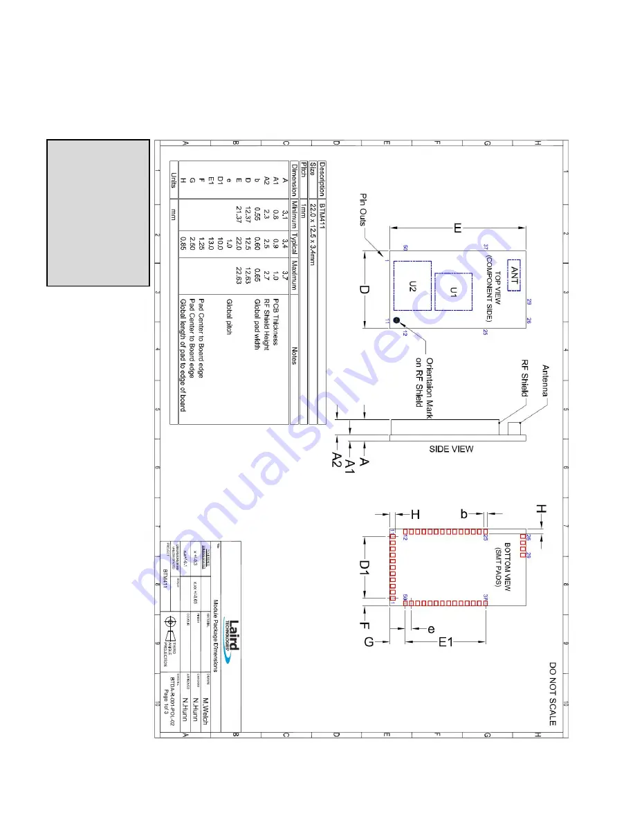
BTM411 Mechanical Details 


Module   
Keep-Out Area 

An area of 1.5mm 
around the module 
should be reserved as 
a keep-out area.   
 
No other components 
should be placed in 
this area. 

Summary of Contents for BTM410

Page 1: ...1 Version 3 0 ...

Page 2: ...ch com Laird Technologies REVISION HISTORY REVISION HISTORY Revision Description Version 1 0 Version 2 0 03 01 2012 Initial Release 12 03 2012 General updates and compliant with firmware v16 1 3 0 Version 3 0 04 13 2012 Reformatting and general edits ...

Page 3: ...rusted Devices 26 AT Commands for Serial Stream Oriented Profiles SSO 27 AT Commands for a Selected Peer Device 31 Bluetooth Profiles 33 Hardware Units BTM410 411 38 Miscellaneous 40 4 Appendix 49 General S Registers 49 ATI Commands 57 Error Responses 59 List of UUIDs 61 References 62 5 FCC Regulatory Statements 63 BTM410 FCC and Industry Canada Statements 63 BTM411 FCC and Industry Canada Stateme...

Page 4: ...Technologies has integrated a complete Bluetooth protocol stack within the modules including support for the Bluetooth Serial Port Profile The modules are fully qualified as Bluetooth End Products allowing designers to integrate them within their own products with no further Bluetooth Qualification They can then list and promote their products on the Bluetooth website free of charge A comprehensiv...

Page 5: ... 232 bi directional for commands and data 16550 compatible Baud Rate Configurable from 1 200 to 921 600bps Non standard baud rates supported Bits 8 Parity Odd even none Stop bits 1 or 2 Default Serial parameters 9600 n 8 1 Levels Set by VDD_USB input Modem Control DTR DSR DCD RI RTS CTS General Purpose Interface I O 8 general purpose I O pins Audio Support 1 PCM channel 64kbps SCO Channels Support...

Page 6: ...r Approval BTM411 CE R TTE Meets CE and R TTE requirements Miscellaneous Lead free Lead free and RoHS compliant Warranty 12 Months Development Tools Development Kit Development board and software tools DVK BTM410 Dev Kit with BTM410 module DVK BTM411 Dev Kit with BTM411 module Pin Definitions Table 2 2 Pin definitions Signal Description Voltage Specification 1 Unused 2 GND 3 UART_CTS Clear to Send...

Page 7: ...See note 3 38 Unused 39 Unused 40 Unused 41 GND 42 GPIO1 UART_RI I O for host VIO 43 GPIO7 UART_ DTR I O for host VIO 44 GPIO8 UART_DSR I O for host VIO 45 GND 46 D Not used for AT module variants VUSB 47 D Not used for AT module variants VUSB 48 GPIO6 I O for host RF_Active VIO 49 GPIO5 I O for host WLAN_Active VIO 50 GPIO3 I O for host BT_Priority VIO Note 1 Unused pins may have internal connect...

Page 8: ...LEVELS MIN TYP MAX Vih 0 7VDD_USB Vil 2 7 VDD_USB 3 0 1 7 VDD_USB 1 9 0 4 0 4 0 8 0 4 Output Voltage Levels 1 7 VDD_USB 1 9 Voh Iout 4mA VDD_USB 0 4 Vol Iout 4mA 0 4 Output Voltage Levels 2 7 VDD_USB 3 0 Voh Iout 4mA VDD_USB 0 2 Vol Iout 4mA 0 2 Note VDD_USB must be connected to power the USB and UART interfaces Table 2 5 Voltage specifications VIO Logic Levels VIO INPUT VOLTAGE LEVELS MIN TYP MAX...

Page 9: ...AT commands which map to various Bluetooth activities The configuration of the device can be saved so that on a subsequent power up the device is discoverable or automatically connects The device has a serial interface which can be configured for baud rates from 1200 up to 921600 default setting is 9600 and an RF communications end point The latter has a concept of connected and unconnected modes ...

Page 10: ...ed Link used for Audio FTP File Transfer Profile GOEP Generic Object Access Exchange Profile GPIO General Purpose Input Output HF Hands free Role of Hands free Profile Hands free Unit HFG Audio Gateway Role of Hands free Profile Hands free Gateway HFP Hands Free Profile HID Human Interface Device Profile HS Headset Role of Headset Profile Headset HSG Audio Gateway Role of Headset Profile Headset G...

Page 11: ...Bluetooth version 2 1 Features SSP EIR SCO 1 eSCO 1 Profiles SPP 1 external codec required Table 3 4 BTM 510 and 511 products BTM510 BTM511 Chipset CSR BC5MM Ext Bluetooth version 2 1 Features SSP EIR SCO eSCO Profiles SPP A2DP AVRCP HSP HFP DUN DT Table 3 5 BTM 520 and 521 products BTM520 BTM521 Chipset CSR BC5MM Ext Bluetooth version 2 1 Features SSP EIR SCO eSCO Profiles SPP A2DP AVRCP HSP HFP ...

Page 12: ...ive 4 All Bluetooth Device Class codes are represented by a fixed 6 digit hexadecimal string case insensitive 5 All profile specific commands are identified by the prefix shown in Table 3 6 Table 3 6 AT command prefix for profiles Profile Term AT Command Prefix Serial Port Profile SPP AT SP Command Syntax The following syntax is employed throughout this document to describe optional or mandatory p...

Page 13: ...de Note that S Register 103 specifies the boot mode from cold Boot modes are required to configure some low level device settings which cannot be configured by S registers and AT commands Currently there are predefined settings defining the PCM data format to be used with certain codec ICs applies mainly to BC04 Response after reset cr lf OK cr lf 4 AT BTC devclasshex Set Device Class Code Tempora...

Page 14: ...ue will become visible on next power cycle which can be initiated by ATZ Refer to number 4 for more information about the device class code Response cr lf OK cr lf 6 AT BTC Read Device Class Code This command is used to read the current device class code Response cr lf 123456 cr lf OK cr lf 7 AT BTF string Set Friendly Name Temporarily This sets the friendly name of this device as seen by other de...

Page 15: ...ice discoverable but not connectable Being discoverable implies that this device will respond to inquiries from other devices inquiry scans enabled The setting remains valid until next reset or power cycle unless not changed by any other AT command subsequently For permanent discoverable connectable settings please refer to S Register 512 Use AT BTX to make the device not discoverable Response cr ...

Page 16: ...sters As with modems the Bluetooth module employs a concept of registers which are used to store parameters such as escape sequence character inquiry delay time etc For a list of general S registers please refer to Table 4 1 in the Appendix S registers associated with a particular profile or specific functions are described in the appropriate profile section of this document The following AT comma...

Page 17: ...te set to 9600 F2 Minimum power consumption UART baud rate set to 38400 F3 Minimum power consumption UART baud rate set to 115200 F4 Medium power consumption UART baud rate set to 115200 F5 Maximum power consumption UART baud rate set to 115200 The new values are NOT updated in non volatile memory until the AT W command is sent to the device Response cr lf OK cr lf Or Response cr lf ERROR nn cr lf...

Page 18: ...g it specifies an AND mask which is used to filter inquiry responses When devclass is 2 hexadecimal characters long it forces the inquiry to filter responses to devices that match their major device class code to this value which can only be in the range 00 to 1F The response format to AT BTI is defined by S Register 330 by bitmask This is device address device class friendly name receiver strengt...

Page 19: ...ult if any further bit is set a comma is inserted as separator 3 RSSI 1 display RSSI value on inquiry result 0 do not display RSSI value on inquiry result if any further bit is set a comma is inserted as separator 4 EIRD 1 display eird on inquiry result 0 do not display eird on inquiry result Inquiry Response format The format of an inquiry result will be cr lf bd_addr dev_class friendly_name rssi...

Page 20: ...ferenced 5 AT BTIE devclass Inquire As per AT BTI but the response comprises for all inquiry responses 1 Bluetooth device address 2 Device class code 3 Friendly name 4 RSSI receiver signal strength indicator 5 Extended inquiry data S register 330 is not referenced 6 AT BTE EIR Data Set up outgoing EIR Data This command sets up outgoing EIR extended inquiry response data Format EIR Data printable A...

Page 21: ...cess Profile Table 5 7 There are 4 Levels providing different levels of security Table 3 10 Table 3 10 Security levels Security Level Characteristics Comment Level 3 MITM protection MITM Man in the Middle attack Encryption User interaction High security Level 2 No MITM protection Encryption Medium Security Level 1 No MITM protection No Encryption 1 Minimal user interaction Low Security Level 0 No ...

Page 22: ...n time limit 3 No input no output The device does not have the ability to indicate yes or no and the device does not have the ability to display or communicate a 6 digit decimal number 4 Reject IO Cap requests IO capability requests prior to SSP are rejected 3 Force Man In The Middle Protection MITM S322 Protection against MITM attacks can be enabled by S332 This S Register only applies if the sec...

Page 23: ...sent immediately on receipt of the AT BTW command Depending on the combination of IO capabilities of both devices one of the asynchronous messages from Table 3 14 might appear during the pairing process Please refer to that table for the required actions On pairing completion an unsolicited message in the form PAIR n bd_addr will be sent to the host 8 S Registers for Secure Simple Pairing The foll...

Page 24: ...yname Example PASSKEY 0016A4000001 Laird BTM 000001 Passkey request Expecting the user to enter the passkey displayed by the remote device Use AT BTB passkey example AT BTB012345 see 1 below PAIR N BdAddr friendlyname Passkey Example PASSKEY N 0016A4000002 Laird BTM 000002 164585 Passkey notification Display BdAddr friendly name and passkey to user Expecting the user to enter the passkey from this...

Page 25: ...is required if not set earlier by AT BTK PIN asynchronous indications will be sent to the host in the form PIN bd_addr where the address confirms the device with which the pairing is to be performed To supply a PIN use the AT BTK command For a successful pairing the link key is stored in a volatile cache which is overwritten every time a new pairing is initiated using this command If S register 32...

Page 26: ...ion 2 pg 37 The value MM indicates the result of the save operation and a value of 00 implies success otherwise the value corresponds to an error code AT Commands Managing Trusted Devices 1 AT BTT List Trusted Device This command is used to list the contents of the trusted device database The link key is NOT displayed so the response is as shown below If the list is empty then just the OK response...

Page 27: ...be transmitted over or received from RF 1 1 Hence as there is only one UART available on a BTM device the UART is not available for other profiles services or module control purposes One approach of managing data and control over UART is to configure local command mode with S531 3 In this mode incoming RF data is presented by the asynchronous message RX string Outgoing data is sent by ATX string o...

Page 28: ... lf Or Response cr lf ERROR 05 cr lf e g string too long 3 Enter Local Command Mode When in data and connected mode and when S 507 is set to 0 or 1 the host can force the device into a command and connected mode so that AT Commands can be issued to the device The character in this escape sequence is specified in the S2 register so it can be changed In addition the escape sequence guard time is spe...

Page 29: ...kbps To cater for this performance hit the device s connection drop capability is configurable to be in one of two modes One mode allows for a connection to be dropped using either method and the other mode allows for a connection drop using the DTR method only By default the device is in the former mode This mode is selected using the S507 register Appendix Table 4 1 To reiterate the escape seque...

Page 30: ...status of the DSR line is to be conveyed to the remote device as a low bandwidth signal then this register MUST be set to 0 otherwise a deassertion of DSR will be seen as a request to drop the Bluetooth connection This register affects S Register 536 see details of 536 S531 0 0 4 Specifies the mode on connection establishment 0 Normal that data is exchanged between UART and RF 1 LOCAL_COMMAND UART...

Page 31: ... If the specified address is 000000000000 then incoming connections are accepted from any device is as per AT BTP without an address The BTM device is not discoverable The setting remains valid until next reset or power cycle unless not changed by any other AT command subsequently For permanent discoverable connectable settings please refer to S Register 512 and AT BTM bd_addr Response cr lf OK cr...

Page 32: ...nce a recovery is possible by one of two methods The first method assumes that the DTR from the host is connected to the DSR line of the module and S507 1 The second method assumes that this connection is absent and S507 1 or 2 In the first method it is enough to deassert the DTR line from the host and that will abort the autoconnect cycle No OK is sent in response Hence it is up to the host to se...

Page 33: ...in S102 value 1 If it was not enabled earlier set the S register accordingly and issue AT W followed by ATZ 2 1 SPP example This section gives an example on how an SPP connection between two Laird BTM devices can be established It is assumed that two devices A and B are connected to a terminal program e g Ezurio Terminal on a PC The example sequence of AT commands is listed in Table 3 16 Figure 1 ...

Page 34: ...omment Enter command mode A or B Response OK Command mode confirmed now AT commands are expected at the UART UART data from host is not sent across to remote device Disconnect AT SPH Response NO CARRIER A and B disconnection confirmed Figure 1 SPP Example Preparation of Device A Figure 2 SPP Example Preparation of Device B ...

Page 35: ... incoming connection which is indicated by the unsolicited string cr lf RING 123456789012 cr lf every second 123456789012 is the Bluetooth address of the connecting device Response cr lf CONNECT 123456789012 1101 cr lf 2 3 AT SPD bd_addr Make Outgoing SPP Connection Initiate an SPP connection to device with Bluetooth address bd_addr and SPP profile The timeout is specified by S register 505 For ba...

Page 36: ...ckward compatibility the following command fulfils the same purpose ATDR Response cr lf CONNECT 123456789012 cr lf Or cr lf NO CARRIER cr lf 2 6 AT SPH Drop SPP Connection Drop an existing SPP connection or reject an incoming connection indicated by unsolicited RING messages For backward compatibility the following command fulfils the same purpose ATH Response cr lf NO CARRIER cr lf 2 7 SPP Incomi...

Page 37: ...456789012 has been established successfully The connection was initiated by the local device outgoing 2 9 SPP S Registers S Registers for SPP are summarized in Table 3 17 below Table 3 17 S Registers for SPP Register Default Range Description S0 0 1 15 Number of RING indication before automatically answering an incoming connection A value of 0 disables autoanswer If 1 then autoanswer on one RING a...

Page 38: ...10 411 device a number of digital I Os can be used for general purposes Each GPIO will be assigned to an S Register S651 to S663 which will be capable of both GPIO configuration config mode as well as single pin read write access r w mode The bitmask of the I O pin for direct read write access will be 0x01 All configuration flags are allocated to higher value bits A bitmask for the I O pin will be...

Page 39: ...pping code must be set in GPIO configuration register 8 15 The pin will carry out the assigned operation and is not accessible anymore as GPIO 0 disable function mapping 1 enable function mapping 4 15 Reserved Table 3 22 GPIO S registers Register GPIO Default Range Description S650 0 0 1 Mode for GPIO Config Registers 0 no mask 1 enable i o pin state Mask S651 GPIO1 0x0000 0 0xFFFF GPIO Configurat...

Page 40: ...g It is recommended to enable all three packet types for eSCO links This will pass the final decision down to the baseband eSCO packets involve a CRC code and retransmission of erroneous eSCO packets Packet types and link types SCO or eSCO are negotiated on link setup A BTM can accept either incoming SCO or eSCO links S register 584 but not both SCO and eSCO at one time If the initiating side requ...

Page 41: ...te AT commands are described on page 23 There is a range of S Registers defining the behavior of automatic link key storage on incoming outgoing and dedicated general bonding 2 1 Dedicated Bonding In BT2 1 specification dedicated bonding is defined as the exchange of link keys between two devices without the intention of establishing a connection immediately Dedicated bonding is initiated by AT BT...

Page 42: ...e automatically default 3 Profile Connection Status The connection status of a profile can be queried by an ATI Command This might be helpful in order to decide whether to disconnect all connected profiles via ATH or a certain one For details please see Table 3 25 Table 3 25 Profile connection status Task AT Command Comment Get connection status of SPP ATI60 0 not connected 1 connected local comma...

Page 43: ...o A2DP connection has existed response NO CARRIER Disconnect AVRCP ATH110E or AT AVH If AVRCP connection released response NO CARRIER 110E If no AVRCP connection has existed response NO CARRIER Disconnect HSG ATH1112 or AT HSGH If AG HSP connection released response NO CARRIER 1112 If no HSP connection has existed response NO CARRIER Disconnect HS ATH1108 or AT HSH Must be enabled by S332 because ...

Page 44: ... not connected response NO CARRIER AT APH ATH110D Response NO CARRIER If A2DP was connected response NO CARRIER 110D If A2DP was not connected response NO CARRIER AT AVH ATH110E Response NO CARRIER If AVRCP was connected response NO CARRIER 110E If AVRCP was not connected response NO CARRIER AT HSH ATH1108 Response NO CARRIER If HS instance was connected response NO CARRIER 110E If HS instance was...

Page 45: ...itching on power hungry circuitry only when needed A slave on the other hand does NOT have prior knowledge of when a packet will be received and has to assume that a packet will be received from a master on every receive slot This means that it has to leave its receiving circuitry on for most of the receive slot duration The result of this is high power consumption on slave side In general a slave...

Page 46: ... slaves attached For this reason the sniff parameters are specified in the BTM module via four S registers S Register 561 is used to specify N S Register 562 is used to specify T and S Registers 563 564 are used to specify minimum M and maximum M respectively Although the specification defines these parameters in terms of timeslots the S register values have to be specified in units of millisecond...

Page 47: ...communicate with it To cater for this circumstance the BTM device will come out of reset using 9600 N 8 1 comms settings for exactly 750 milliseconds and then revert to the communication parameters as per the S Registers If the host sends the string BISM cr where cr is the carriage return character within hat 750ms period then the module will remain at 9600 N 8 1 and will also configure itself usi...

Page 48: ...125 milliseconds Ezurio Terminal provides a BREAK capability which can be used to reset a connected BTM device by ticking and un ticking the BRK field see Figure 7 Figure 7 BREAK capability in Ezurio Terminal 15 Append Bluetooth Address to Friendly name If S Reg 593 is set to 1 then the last 6 hex digits of the Bluetooth address are automatically appended to the friendly name This allows multiple ...

Page 49: ...nt Depending on supported profiles Defines a set of bits masks for enabling profiles Values can be ORed A profile can be enabled only if it is supported by the BTM variant Issue AT W and ATZ in order to make the new setting effective 0x001 is Serial Port Profile 0x002 is Headset HS 0x004 is DUN 0x008 is Audio Gateway Headset HSG 0x010 is Handsfree HF 0x020 is OBEX FTP 0x040 is Audio Gateway Handsf...

Page 50: ...arantees the minimum delay Note that for invalid addresses specified in the ATD command the NO CARRIER response will be immediate See S register 560 for specifying disconnect max timeout S506 0 0 1 Enable Disable echoes The ATEn command also affects this S507 0 0 2 When set to 0 a connection can be dropped using escape sequence only and the state of DSR line is ignored When set to 1 a connection c...

Page 51: ...ult Device Class Code When queried the value is always printed as a hexadecimal number To change the device class of the module temporary and immediately without power cycle use the command AT BTC To change the device class of the module permanently write the new value to this S Register ATS515 devclasshex save the setting AT W and initiate a power cycle ATZ S516 000000 0 2FFFFFF Default Device Cl...

Page 52: ...at a non standard baud rate is requested it is entirely possible that the host is not capable of generating such a baud rate In this case the BTM device cannot be communicated with If this happens there is a procedure to recover from this situation which is described in section 12 pg 42 Factory Default UART Baud Rate S523 1 1 2 Number of Stop bits See S Register 526 for further information S524 0 ...

Page 53: ...ted Bit 0 for HV1 Bit1 for HV2 and Bit2 for HV3 When the connection is lost the SCO channel disappears along with it S535 20 0 41 Link Supervision Timeout If units go out of range then a NO CARRIER message will be sent to the host after the time specified here S536 0 0 1 When set to 1 a remote device can capture the AT parser of this unit by it sending this module an escape sequence The inter char...

Page 54: ...top sending any data back S552 0122 0 fff This register specifies in each 4 bit nibble how the DTR DCD RI output pins are controlled when in a Bluetooth connection Nibble 0 3 specifies the source for DTR 4 7 specifies the source for DCD 8 11 specifies the source for RI Each nibble can take the following value 0 Do NOT touch the I O 1 Always deassert 2 Always assert 3 If RTC bit in CONTROL_IND is 1...

Page 55: ...n S Reg 569 S558 0 0 1 When 1 the following responses RING NO CARRIER and CONNECT are replaced by BTIN BTDOWN and BTUP respectively This will eliminate ambiguity when the module has a Bluetooth connection to an AT modem which also gives these responses S559 0 0 3 This specifies a mask When Bit 0 is 1 the response word ERROR is replaced by BTERR and OK is replaced by ok When Bit 1 is 1 then error r...

Page 56: ...imeout defined in SReg 554 instead of mode defined in SReg555 S569 1 1 7 If S565 1 and RI is de asserted then this is the mode the device will assume after the post start up timeout defined in SReg 554 instead of mode defined in SReg555 S584 0 0 1 Enable Disable eSCO S588 0 0 1 After a disconnection there will be a cold reset S592 0 0 1 Set this to 1 to reduce the trusted device database to just 1...

Page 57: ...cturer of the Bluetooth chipset ATI8 The chipset format ATI9 SPP connection status 0 not connected 1 connected in local command mode 2 connected in remote command mode ATI11 The reason why a NO CARRIER resulted in the most recent attempt at making an outgoing connection Where the response values are as follows 0 No prior connection 1 Connection timeout 2 Connection attempt cancelled 3 Normal disco...

Page 58: ...ble and or discoverable where the lowest significant digit equates to the value stored in S Register 512 or 555 Note when n 16 ATI9 will return 1 ATI60 SPP connection status 0 not connected 1 connected identical with ATI9 ATI61 A2DP connection status 0 not connected 1 connected ATI62 AVRCP connection status 0 not connected 1 connected ATI63 HSP Headset connection status 0 not connected 1 ACL conne...

Page 59: ...ce Class Code 09 Invalid Bluetooth Address 10 Could not set Service or Friendly name 11 PS Store Write 12 PS Store Read 13 Not Idle 14 Incorrect Mode 15 Already Scanning 16 Pairing is already in progress 17 Not USED 18 Not USED 19 Not USED 20 Not safe to write to Non volatile Store Ongoing Bluetooth Connection 21 Link Key Cache is Empty 22 Link Key Database is Full 23 Malloc returned NULL Resource...

Page 60: ... Command or operation not allowed 46 No A2DP role has been set see S register 300 47 No AVRCP role has been set see S register 301 48 No AVRCP category has been set see S register 302 49 No AVRCP control connection 50 No A2DP or AVRCP connection currently incoming 51 Invalid operation ID AVRCP 52 Wrong AVRCP role 53 Command disabled by S Register 310 54 No manufacturing information available 55 Au...

Page 61: ...UUIDs UUID Mnemonic Profile Role 0x1101 Serial Port Profile SPP 0x1102 LAN access using PPP 0x1103 Dial up Networking DUN 0x1105 OBEX Object Push 0x1106 OBEX File Transfer 0x1108 Headset Profile HSP Headset 0x110A A2DP Audio Source 0x110B A2DP Audio Sink 0x110C AVRCP Remote Target 0x110D A2DP 0x110E AVRCP 0x110F AVRCP Remote Controller 0x1112 Headset Profile Audio Gateway 0x111E Hands free Profile...

Page 62: ...e list of Profile UUIDs click on Assigned Numbers Service Discovery 4 Class of Device Generator this link might be helpful for creating a particular CoD http bluetooth pentest narod ru software bluetooth_class_of_device service_generator html Caution this tool allows selection of more than one minor device classes so make sure that only one minor device class is select and verify the result with 3...

Page 63: ...smitter must be installed to provide a separation distance of at least 20 cm from all persons and must not be co located or operating in conjunction with any other antenna or transmitter This module was approved with the following antenna RF Solutions ANT 24G WHJ SMA 0dBi Operation of this module with any other antenna will require additional testing to be performed Co location with other radio tr...

Page 64: ...o provide a separation distance of at least 20 cm from all persons and must not be co located or operating in conjunction with any other antenna or transmitter Co location with other radio transmitting devices operating concurrently in the same band will require additional testing and certification Designers should note the distinction that the FCC makes regarding portable and mobile devices Mobil...

Page 65: ...00 A2 2006 ClassB Immunity EN61000 4 2 1995 A1 1998 A2 2001 EN61000 4 3 2002 A1 2002 3 2 Means of the efficient use of the radio frequency spectrum EN 300 328 V1 7 1 2006 10 Declaration We Ezurio Ltd declare under our sole responsibility that the essential radio test suites have been carried out and that the above product to which this declaration relates is in conformity with all the applicable e...

Page 66: ...ssB Immunity EN61000 4 2 1995 A1 1998 A2 2001 EN61000 4 3 2002 A1 2002 3 2 Means of the efficient use of the radio frequency spectrum EN 300 328 V1 7 1 2006 10 Declaration We Ezurio Ltd declare under our sole responsibility that the essential radio test suites have been carried out and that the above product to which this declaration relates is in conformity with all the applicable essential requi...

Page 67: ... link provides an overview of the EPL system the user will be required to register login first https www bluetooth org login register https www bluetooth org technical qualification eploverview htm For a detailed procedure of how to make an EPL entry please refer to the following SIG document https www bluetooth org docman handlers DownloadDoc ashx doc_id 71880 Additionally there is on EPL online ...

Page 68: ...lairdtech com Laird Technologies MECHANICAL DRAWINGS 8 MECHANICAL DRAWINGS BTM410 Mechanical Details Module Keep Out Area An area of 1 5mm around the module should be reserved as a keep out area No other components should be placed in this area ...

Page 69: ...ule 69 www lairdtech com Laird Technologies MECHANICAL DRAWINGS BTM410 Mechanical Details Module Keep Out Area An area of 1 5mm around the module should be reserved as a keep out area No other components should be placed in this area ...

Page 70: ...ule 70 www lairdtech com Laird Technologies MECHANICAL DRAWINGS BTM411 Mechanical Details Module Keep Out Area An area of 1 5mm around the module should be reserved as a keep out area No other components should be placed in this area ...

Page 71: ...ule 71 www lairdtech com Laird Technologies MECHANICAL DRAWINGS BTM411 Mechanical Details Module Keep Out Area An area of 1 5mm around the module should be reserved as a keep out area No other components should be placed in this area ...

Page 72: ...BTM410 411 Bluetooth AT Data Module 72 www lairdtech com Laird Technologies MECHANICAL DRAWINGS BTM411 Mechanical Details ...

Page 73: ...BTM410 411 Bluetooth AT Data Module 73 www lairdtech com Laird Technologies MECHANICAL DRAWINGS Development Kit Schematic ...

Page 74: ...BTM410 411 Bluetooth AT Data Module 74 www lairdtech com Laird Technologies MECHANICAL DRAWINGS ORDERING INFORMATION APPLICATION NOTE FOR SURFACE MOUNT MODULES Development Kit Schematic ...

Page 75: ...ys are provided in Figures 8 and 9 0 906 0 742 0 164 0 750 0 664 0 086 0 578 0 578 Detail B Detail A Detail A R 0 050 Detail B R 0 50 88 0 Pocket Wall Angles Top and Bottom Radius r 0 025 0 597 0 761 1 339 1 503 1 697 2 797 3 897 4 997 6 097 7 197 8 297 9 397 10 497 12 000 0 313 0 156 0 0 0 010 0 450 0 536 1 114 1 200 1 350 2 250 3 150 4 050 0 0 0 0 5 250 Laird 5200 00022 Notes 1 Material must be ...

Page 76: ...re Temperatures should not exceed the minimums or maximums presented in Table 9 1 Table 9 1 Recommended Maximum and minimum temperatures Recommended Max Min s Specification Value Unit Temperature Inc Dec Rate max 3 C Sec Temperature Decrease rate goal 2 3 C Sec Soak Temp Increase rate goal 5 1 C Sec Flux Soak Period Min 60 Sec Flux Soak Period Max 90 Sec Flux Soak Temp Min 150 C Flux Soak Temp max...

Page 77: ...velopment board with BTM411 module soldered in place General Comments This is a preliminary datasheet Please check with Laird Technologies for the latest information before commencing a design If in doubt ask Refer to the schematic BTDMD R 001 pdf for the Development Kit on the following two pages for examples of typical pin connections A PDF of the schematic can be downloaded from the product web...

Page 78: ...of this product without obligation to notify any person or entity of such revision Copying duplicating selling or otherwise distributing any part of this product or accompanying documentation software without the prior consent of an authorized representative of Laird Technologies Inc is strictly prohibited All brands and product names in this publication are registered trademarks or trademarks of ...

Reviews: