


LAGUNATOOLS.COM
26
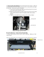
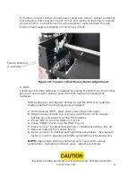
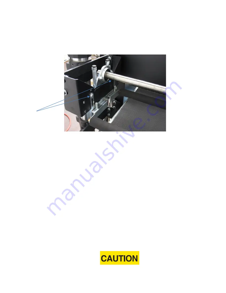
5. Confirm correct contact of hold-down (pressure) rollers. Adjust contact by
loosening the roller bracket in each corner and raising or lowering to provide
proper tension. Correct tension is achieved when material feeds through
brush properly without slipping on the conveyor belt.
Figure 18: Tension (Hold-Down) Roller Adjustment
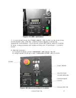
6. DRO;
Install two CR-2032 batteries (included) by pulling the DRO from the Control
Box and removing the battery cover from the back and installing the
batteries.
DRO Calibration; the typical method to use the DRO is to read the
bristle penetration into stock being processed.
A. With machine “OFF”, place stock under the brush head.
B. Adjust conveyor table (up or down) until the tip of the longest
bristles are just about touching the material.
C. Press “ON” to turn the DRO on
, Fig. 19.
D. Press “ZERO” to zero out the DRO
, Fig. 19.
E. Press “in/mm” to select desired inch or millimeter setting
, Fig. 19.
F. Remove material from under brush.
G. Raise conveyor to desired setting/bristle penetration. See sample
letter or confirm appropriate bristle penetration with salesperson.
NOTE:
Appropriate bristle penetration will change with various
applications, materials and brush wear. Adjust accordingly.
Excessive bristle penetration will prematurely shorten brush life!
Tension Roller Adj.
(2 each side)
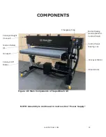
Summary of Contents for SuperMax SuperBrush 49
Page 1: ...OWNERS S MANUAL SuperBrush 49 Lagunatools com...
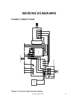
Page 23: ...LAGUNATOOLS COM 23 WIRING DIAGRAMS POWER CONNECTIONS Figure 14 Power Connections Wiring...
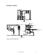
Page 24: ...LAGUNATOOLS COM 24 INTERNAL WIRING Figure 15 Internal Wiring...
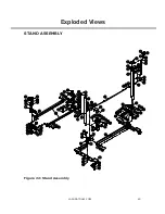
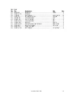
Page 30: ...LAGUNATOOLS COM 30 Exploded Views STAND ASSEMBLY Figure 22 Stand Assembly...
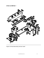
Page 33: ...LAGUNATOOLS COM 33 HEAD ASSEMBLY Figure 23 Head Assembly without brush...
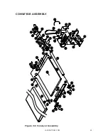
Page 35: ...LAGUNATOOLS COM 35 CONVEYOR ASSEMBLY Figure 24 Conveyor Assembly...