background image


Thank you for investing in a PX12 Planer by Laguna Tools.  This planer 

is one of a family of unique machines proudly offered by Laguna Tools.  
Every Laguna machine is engineered for years of dependable service.  

Please  feel  free  to  contact  Laguna  Tools  if  you  have  a  question  or 
suggestion.    We  appreciate  working  with  you  and  your  choice  of  a 

Laguna Tools machine for your shop.   
 

Regards, 
Torben Helshoj 

President & Founder Laguna Tools 


Dealer Machinery Warranty 

New  woodworking  machines  sold  by  Laguna  Tools  carry  a  two-year  warranty  effective 
from  the  date  of  dealer  invoice  to  consumer.  Machines  sold  through  dealers  must  be 
registered with Laguna Tools within 30 days of purchase to be covered by this warranty. 
Laguna  Tools  guarantees  all  new  machine  sold  to  be  free  of  manufacturers’  defective 
workmanship,  parts  and  materials.  We  will  repair  or  replace,  without  charge,  any  parts 
determined  by  Laguna  Tools,  Inc.  to  be  a  manufacturer’s  defect.  We  require  that  the 
defective  item/part  be  returned  to  Laguna  Tools  with  the  complaint.  An  RMA  (return 
merchandise authorization) must be requested, from Laguna Tools, and included with any 
and  all  parts  or  machines  returned  to  Laguna  Tools  for  warranty  consideration.  Any 
machines returned to Laguna Tools must be returned with packaging in the same manner 
in  which  it  was  received.  If  a  part  or  blade  is  being  returned  it  must  have  adequate 
packaging to ensure no damage is received during shipping. In the event the item/part is 
determined  to  be  damaged  due  to  lack  of  maintenance,  cleaning  or  misuse/abuse,  the 
customer will be responsible for the cost to replace the item/part, plus all related shipping 
charges. This limited warranty does not apply to natural disasters, acts of terrorism, normal 
wear and tear, product failure due to lack of maintenance or cleaning, damage caused by 
accident, neglect, lack of or inadequate dust collection, misuse/abuse or damage caused 
where repair or alterations have been made or attempted by others. 

This manual applies to the PX12 Planer.  Enter the model number and serial 
number below for quick reference when ordering accessories, supplies or parts.  

NOTE:  The  model  and  serial  number  plate  can  be  found  on  the  side  of  the 
planer.    


Model: ___________ 


Serial: ___________ 
  

Laguna Tools                                                    744 Refuge Way, 
Suite 200           

Grand Prairie                                                    TX 75050                      
 

                    800-234-1976                   

www.lagunatools.com 

Summary of Contents for PX12

Page 1: ...OWNERS S MANUAL PX12 Planer Quadtec I Cutterhead Lagunatools com...

Page 2: ...must be requested from Laguna Tools and included with any and all parts or machines returned to Laguna Tools for warranty consideration Any machines returned to Laguna Tools must be returned with pack...

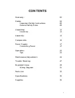
Page 3: ...05 General Safety Rules 09 Unpacking 12 Inventory 13 Assembly 13 Components 16 Power Supply 17 Connecting Power 17 Operation 22 Tips 23 Maintenance Adjustment 24 Trouble Shooting 27 Exploded Views 29...

Page 4: ...tecting YOUR SAFETY and PREVENTING EQUIPMENT PROBLEMS To help you recognize this information we use the symbols below Please read the manual and pay attention to these sections Indicates an imminently...

Page 5: ...strongly recommend that this machine not be modified and or used for any application other than that for which it was designed If you have any questions relative to a particular application DO NOT us...

Page 6: ...arnings may cause serious injury 2 Replace the warning labels if they become obscured or removed 3 This SuperBrush is designed and intended for use by properly trained and experienced personnel only I...

Page 7: ...adjusting keys wrenches scrap stock and cleaning rags are removed away from the machine before turning on 14 Keep safety guards in place at all times when the machine is in use If removed for maintena...

Page 8: ...g and changing accessories 26 Turn off the machine before cleaning Use a brush or compressed air to remove dust or debris do not use your hands 27 Do not stand on the machine Serious injury could occu...

Page 9: ...r use of the unit properly repair or replace any part that is damaged FAILURE TO FOLLOW THESE RULES MAY RESULT IN SERIOUS INJURY ADDITIONAL SAFETY INFORMATION Intended use This machine is intended for...

Page 10: ...dust lines are thoroughly grounded by using a grounding wire Regular cleaning Regularly check the machine for excessive dust and debris and clean Make sure to regularly clean the surrounding area wher...

Page 11: ...th or without yellow stripes is the equipment grounding wire If repair or replacement of the power cord or plug is necessary do not connect the equipment grounding wire to a live current carrying term...

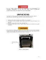
Page 12: ...emove the crate covering the machine if so packed 2 Carefully cut the banding straps and remove them from the box if so packed 3 Remove the box from the crate and open box 4 Using the information belo...

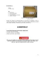
Page 13: ...r to machine assembly and use read this manual thoroughly to familiarize yourself with proper assembly maintenance and safety procedures ASSEMBLY Tools items Required Assembly Adjustment T 25 Torx wre...

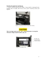
Page 14: ...exposed stud aligning flat of handle with flat of stud insert mounting screw and tighten Figure 3 Installing Thickness Adjustment Handle The Carriage Lock must be UP unlocked when turning the Thicknes...

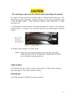
Page 15: ...hardware to mount to the outfeed side of planer 3 screws one on each side and one underneath the dust chute Figure 4 Dust Chute 4 Attach dust collector to dust chute NOTE Make sure the dust collectio...

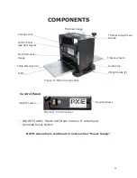
Page 16: ...rotation of cutterhead Overload Reset Button NOTE Assembly is continued in next section Power Supply Stock Removal Gauge Lifting Handle 2 Thickness Scale Table Depth Stop Table Extension 2 Thickness...

Page 17: ...IN ALL CASES MAKE CERTAIN THE RECEPTACLE IN QUESTION IS PROPERLY GROUNDED IF YOU ARE NOT SURE HAVE A QUALIFIED ELECTRICIAN CHECK THE RECEPTACLE MOTOR SPECIFICATIONS The typical main motor is 2 HP and...

Page 18: ...cutterhead 2 Make sure the Carriage Lock is unlocked UP position 2 Use the Table Height Adjustment handle Fig 8 A to raise the table until the infeed roller is approximately 1 16 above the calibratin...

Page 19: ...e two screws of the Thickness Scale pointer and adjust the pointer Fig 7 until it corresponds to the measured thickness and tighten the screws Thickness Gauge The top of the planer is a thickness gaug...

Page 20: ...riage until desired stock removal appears on gauge Pull stock from machine Process stock as described in Operation Depth Stop The depth stop is located on the side of the planer Fig 10 It has four set...

Page 21: ...extension tables to be lower than the main bed The extension tables should never be higher than the main bed under the cutterhead 3 If adjustment is needed raise the extension table requiring adjustm...

Page 22: ...to support stock 2 Establish the proper depth of cut typically less than 1 16 using the Thickness Adjustment handle and referencing the Thickness Scale or the Material Removal Scale Figure 12 Thicknes...

Page 23: ...stock until it has exited the outfeed roller TIPS Planers are most effective if one face of stock is flat If not flatten one face with a jointer or drum sander If not possible to flatten one face pro...

Page 24: ...T20 to remove the knife insert screw Use a second Torx wrench to hold the cutterhead from rotating in position in another screw DO NOT USE YOUR HAND TO HOLD THE CUTTERHEAD See Fig 14 NOTE The dust ch...

Page 25: ...ting properly and may affect the quality of the cut Before installing each screw lightly coat the screw threads with machine oil and wipe off any excess Securely tighten each screw which holds the kni...

Page 26: ...e with the next steps 4 To adjust tension loosen the socket head hex cap screw in the center of chain tension arm Fig 16 Figure 16 Chain Tension NOTE Do not allow the chain to fall from the sprockets...

Page 27: ...rd replaced 3 Check connection 4 Check voltage 5 press reset switch on control panel Cutterhead does not come up to speed 1 Low current 2 Motor not connected to correct voltage 1 Contact local electri...

Page 28: ...r 1 Inadequate feed roll pressure 2 Planer bed dirty 3 Dirty feed rollers 4 Incorrect setting for in feed out feed rollers 1 Adjust feed roll tension or lower feed rollers 2 Clean pitch and residue of...

Page 29: ...29 EXPLODED VIEWS Cutterhead Drivetrain...

Page 30: ...30 Table Lift...

Page 31: ...31 Motor...

Page 32: ...32 Wiring Diagram PX12 PARTS LIST...

Page 33: ...200111 615 Sponge 2mm 1 10 923507 000 Torx Wrench T30 1 11 001601 101 Round Head Phillip Screw Washer M4 0 7x8 4 10x0 8 11 12 029301 101 Torx Screw w Lock Washer M5 0 8x10 5 1x7 9 2 13 924827 001 Def...

Page 34: ...37 010006 000 Retaining Ring STW 15 2 38 000302 102 Round Head Phillips Screw M4 0 7x8 3 40 250114 615 Dust Port 1 41 250133 615 Connector 1 42 000002 111 Hex Screw M6 1 0x20 6 43 008005 100 Hex Nut M...

Page 35: ...ll Bearing 6202 1 66 010103 000 Retaining Ring RTW 35 1 Key Part No Description Specifications Qty 67 250086 615 Chain Cover 1 68 160031 000 Spacer 1 69 280037 000 Spring 1 70 000304 102 Round Head Ph...

Page 36: ...21102 000 Cord Clamps ACC 2 5 1 98 910140 000 Motor Assembly 110V 120V 1 99 2 575140 000 Scale 1 99 6 575545 000 Material Remove Gauge Scale 3 32 1 108 010002 000 Retaining Ring STW 11 1 109 006003 00...

Page 37: ...N OFF for main motor Packing Size L x W x H 25 x 17 x 21 5 635 x 432 x 546 mm Machine weight 65 lbs 30 kg Shipping weight 72 lbs 33 kg SUPPLIES Replacement knives Replacement knife screws Contact Lagu...

Page 38: ...38 021121...
Reviews: