background image


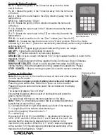
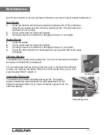
Emergency stop 

button 


Start button 


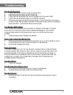
Controller Note may vary 

from that shown 

Controller Button Functions

X+ / 1 

= Moves the gantry in the X direction away from the home 

end of the bed.

Y+ / 2 

= Moves the gantry in the Y direction away from the home end 

of the bed.

Z+ / 3 

= Moves the router head in the Z [Up direction] away from the 

table surface.

XY-0 / 4 

= Sets machine “Origin”.

X- / 5 

= Moves the gantry in the X direction towards the home end 

of the bed.

Y- / 6

 = Moves the router head in the Y direction towards the home 

end of the bed.

Z- / 7 

= Moves the router head in the Z [Down direction] towards the 

table surface.

Z-0 / 8 

= Is used to set the tool to the “Zero” surface [tool “touch-off”].

HOME / 9

 = Causes the machine to move to the “Home” position, First in the Z axis, 

followed by X and then Y. [Home is a mechanically determined position using mechanical 

switches/sensors.]

HIGH/LOW / 0 

= Toggles jogging speeds between High and Low ranges.

ON/OFF 

= Turns the Router Spindle On and Off.

MENU / _ 

= Provides access to various setup features.

ORIGIN /OK

 = Use to accept commands [“On”]. Origin causes machine to return to the 

machines “Origin”.

MODE

 = Toggles between the three jogging modes: Continuous, Step or Distance.

RUN PAUSE / DELETE

 = Used to load a program from either the USB drive or

internal memory. While the program is running, causes the Operation to “Pause”.

STOP / CANCEL 

= Stops a running program. Also used to cancel commands.

Turning on the Machine

Note:

 Before you turn on the machine remove all tools and other objects 

from the machine table.

Release the emergency stop by twisting clock wise and it will pop out.

Press the green start button, this will turn power on to the machine.

Pressing the green button will also power the controller and the display 

will light up.

The screen will display “Go to Home?”

Ensure that the table surface is clear of obstructions and press the 

green Origin/OK button.

The router head will move to the home position on the table.

Note: 

“Home” is a mechanical position that is a constant determined 

by switches on each of the 3 axes.

X+= Across [from left-to-right when standing in front of the machine]

Y- = Length [from front-to-back when standing in

front of the machine]. Should this be Y+?

Z+= vertical [up].

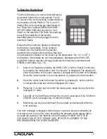
By pressing HIGH LOW / 0 and MENU / - the display will change to 

AX=0, AY=0, and AZ=0. When the X, Y and Z have an A in front, this

denotes that the dimensions displayed are in reference to the 

machine’s home position. When the X, Y, and Z values are displayed 

with a number [1-9] this indicates the dimensional relationship of the 

machine from the machine’s “Origin”.

16

Summary of Contents for Laguna Series

Page 1: ...nual LAGUNA TOOLS 2072 Alton Parkway Irvine California 92606 Ph 800 234 1976 www lagunatools com 2017 Laguna Tools Inc LAGUNA and the LAGUNA Logo are the registered trademarks of Laguna Tools Inc All...

Page 2: ......
Page 3: ...supplying distributor Read carefully before operating the machine 1 Keep the working area clean and be sure adequate lighting is available 2 Do not wear loose clothing gloves bracelets necklaces or o...

Page 4: ...empted by others Laguna Tools Inc is not responsible for additional tools or modifications sold or performed other than from by Laguna Tools Inc on any Laguna Tools Inc machine Warranty maybe voided u...

Page 5: ...tor 3 hp very quiet spindle 3 hp very quiet spindle 3 hp very quiet spindle Spindle 1 or 3 Phase Industrial Induction Spindle Liquid Cooled 1 or 3 Phase Industrial Induction Spindle Liquid Cooled 1 or...

Page 6: ...shipping to customers as movement can take place during transportation It must be noted that additional machine movement can take place between Laguna Tools and the end user and some adjustments may...

Page 7: ...le is moved along the gantry by a precision ball screw system that is controlled by the machine controller 4 Frame The frame is a heavy welded construction that supports all the other parts of the mac...

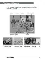
Page 8: ...lets Memory stick Dust hose clamps Tools Memory stick Controller cable Water pump Controller CD 8 What You will Receive Note The quantity of collets cutters and clamps will vary from that shown depend...

Page 9: ...g the tin snips cut the banding that is securing the machine to the pallet if fitted WARNING EXTREME CAUTION MUST BE USED AS THE BANDING WILL SPRING AND COULD CAUSE INJURY 2 Remove the box from the Sw...

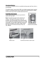
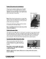
Page 10: ...or similar Teflon tends to dry and will not attract sawdust and dirt Assembling the Controller Fit the cable to the controller and ensure that the screws are finger tight Note The cable has plugs at...

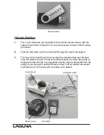
Page 11: ...st hose support 3 The head of the machine will move across the complete table and the dust hose will follow the head If there is insufficient slack the hose may break or damage the dust shroud It is s...

Page 12: ...ed electrician must carry out the electrical installation Fitting the Vacuum Pump The machine is provided with a 2 inch hose for connection to your vacuum pump The hose connects to the vacuum manifold...

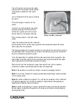
Page 13: ...you do not want to kick the container and spill the water Once the assembly is complete and the water pump electrical connection has been made plug the pump into the machine water pump socket lift the...

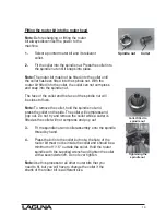
Page 14: ...the face of the spindle nut will be close to flush Note To remove the collet hold the spindle nut and press the collet on the side The collet will compress and pop out Do not try and remove the colle...

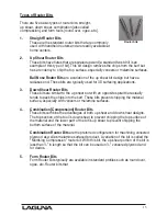
Page 15: ...ar to the up shear but with an opposite spiral that actually tends to pack the chips into the kerf These bits prevent chipping the material surface especially with veneers or melamine surfaces 4 Combi...

Page 16: ...USE DELETE Used to load a program from either the USB drive or internal memory While the program is running causes the Operation to Pause STOP CANCEL Stops a running program Also used to cancel comman...

Page 17: ...rd time and Distance is displayed This allows you to input the position into the controller that you want the router spindle to move to As an example If you want to move the router spindle 100mm from...

Page 18: ...ordinates e g 1 9 1 Select Low Speed by pressing the HIGH LOW 0 button Select Continuous by pressing the mode button until Continuous is displayed The display will show the position of the router head...

Page 19: ...ble and is compressed by the spoil board sometimes called sacrificial board as the vacuum is applied T slots are also provided to allow you to clamp jobs spoil boards to the table should it be require...

Page 20: ...otect the vacuum table from the cutters You will set the depth of your cutter a few thousandths of an inch deeper than the job thickness If there was no spoil board this would mean that you would be c...

Page 21: ...d 1 Cut your spoil board to the size of the bed of the machine 2 Place on the vacuum table Prior to placing the spoil board onto the vacuum table ensure that the table is perfectly clean free from saw...

Page 22: ...this will not be a problem as the changes from day to day are not significant Also the changes will in general be over the complete board There are however exceptions Your morning coffee can do a grea...

Page 23: ...bottom router bit to the spindle 2 Jog Z the tip of the tool down so that it is just above the top of the spoil board using the Continues CONTINUOUS button 3 Step down in slow mode 0 1mm 0 004 each ti...

Page 24: ...ctly under the point of the router bit and adjust the spoil board position so that it is parallel with the edges of the vacuum table Vacuum can now be applied to the spoil board Re Setting the Origin...

Page 25: ...r of the machine as the spindle will start to turn and could cause injury 8 The router will just cut the surface of the spoil board the distance that you set in the design software we suggest 1 6mm 1...

Page 26: ...ess 3 Generally inspect the machine for damage and loose or worn parts 4 Check the dust extraction for blockages and any large bits that could cause blockages Oiling the Machine The machine is provide...

Page 27: ...lty Replace the breaker Motor Tries To Start But Will Not Turn 1 With the power disconnected from the machine try to turn the spindle by hand If the spindle will not turn check the reason for the jamm...

Page 28: ...ations subject to change Machines may be shown with optional accessories 2017 Laguna Tools Inc LAGUNA and the LAGUNA Logo are the registered trademarks of Laguna Tools Inc All rights reserved 2072 Alt...

Reviews: