background image


26 

NO. 


DESCRIPTION 


Q’TY 


NO. 


DESCRIPTION 


Q’TY 


STAND 


51 


SCREW M5x10 


BED 


52 


BRACKET 


SCREW M5x12 


53 


C-RING  C-19 


SPRING WASHER 5 


54 


LEVER 


BAFFLE 


55 


POWER CORD 


WASHER 8 


56 


STRAIN RELIEF 


CAP SCREW  M8x35 


57 


MOTOR 


C-RING  C-19 


58 


KNOCKOUT ROD 


SET SCREW M5x10 


59 


SCREW M5x12 


BAFFLE 


60 


PLATE 


11 


TOOL REST BODY 


61 


KEY 6X6X48 


12 


TOOL REST 


62 


CAP SCREW  M10x30 


13 


TOOL SUPPORT HANDLE 


63 


HANDLE 


14 


TOOL SUPPORT ROD 


64 


WASHER 10 


CENTRE 


65 


MOTOR ASSEMBLY PLATE 


16 


QUILL 


66 


KNOB 


17 


LEAD SCREW 


67 


SET SCREW  M6X12 


18 


TAILSTOCK ROD 


68 


MOTOR PULLEY 


19 


TAILSTOCK QUILL HANDLE 


69 


NUT M12X1 


SET SCREW  M8X12 


70 


SCREW M4x8 


21 


HANDLE 


71 


BRACKET 


22


 HANDLE WHEEL 


72 


DIGITAL READER 


23 


TAILSTOCK 


73 


HEX NUT M18 


24 


PIN  5X50 


74 


CLAMP  


C-RING  C-19 


75 


CLAMP BOLT 


26 


CLAMP BOLT 


76 


BUSHING 


27 


BUSHING  


77 


KEY 5x5x32 


28 


KEY 5x5x32 


78 


C-RING C--4 


29


 HEX NUT M18 


79 


RUBBER 


BUSHING 


80 


SCREW M5x12 


31 


CLAMP 


81 


BELT DOOR 


32 


SUPPORT BRACKET 


82 


SPEED LABEL 


33 


HEADSTOCK SPUR 


83 


KNOB 


34 


FACEPLATE 


84 


SCREW M4x10 


SET SCREW  M6X12 


85 


ON/OFF SWITCH 


36 


SPINDLE 


86 


VARIABLE SPEED KNOB 


37 


KEY  8X7X45 


87 


SCREW M4x10 


38 


C-RING  C-30 


88 


FWD/REV SWITCH  ZH-D 


39 


BEARING   6206 


89 


PANEL COVER 


C-RING  C-62 


90 


SCREW M4x10 


41 


BEARING   6206 


91 


SCREW M4x10 


42 


HEADSTOCK 


92 


DIGITAL READOUT 


43 


POLY-V BELT 530J6 


93 


HEX HEAD BOLT 


44 


SPINDLE PULLEY 


94 


SWITCH BOX 


INVERTER 


95 


C-RING C-19 


46 


SCREW M5x45 


96 


47 


SCREW M4x10 


97 


Summary of Contents for Platinum 18/47 Series

Page 1: ...LAGUNA TOOLS 2072 Alton Parkway Irvine California 92606 Ph 800 234 1976 www lagunatools com Model Numbers L A175017 2018 Laguna Tools Inc LAGUNA and the LAGUNA Logo are the registered trademarks of La...

Page 2: ......

Page 3: ...Noise emission 6 Specification sheet 6 Receiving your machine 7 Introduction to your machine 7 Parts of the machine 7 Where to locate your machine 11 Unpacking your machine 11 Assembly and setup 13 Ma...

Page 4: ...r Read the following carefully before operating the machine 1 Keep the working area clean and be sure adequate lighting is available 2 Do not wear loose clothing gloves bracelets necklaces or ornament...

Page 5: ...empted by others Laguna Tools Inc is not responsible for additional tools or modifications sold or performed other than from by Laguna Tools Inc on any Laguna Tools Inc machine Warranty maybe voided u...

Page 6: ...xample adjacent machines in other words the level of ambient noise It is possible that exposure level limits will vary from country to country Specification sheet Motor 2 HP TFEC Voltage 220V Swing ov...

Page 7: ...u will find sawdust within your machine This is because the machine has been tested prior to shipment from the factory and or Laguna Tools Laguna Tools endeavors to test machines prior to shipping to...

Page 8: ...8 Lathe bed The bed is a machined heavy casting...

Page 9: ...rol and motor The speed can be adjusted between 0 1200 low 0 3200 high The spindle has an indexing pin that allows it to be locked in 16 positions Tail stock Tool rest Tail stock The tail stock is a c...

Page 10: ...ed to suite the job in hand Electrical System The electrical control system is housed inside the head stock and a power cord with a 3 pin plug is provided What you will receive with your lathe Boxed l...

Page 11: ...for adjustments and maintenance to be conducted 3 Adequate lighting The better the lighting the more accurately and safely you will be able to work 4 Solid floor You should select a solid flat floor p...

Page 12: ...unting bolts that secure the machine to the base of the box 4 It is recommended that the bed of the machine be removed from the packaging by lifting it with a hoist or forklift using a SLING Remove th...

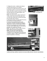
Page 13: ...bly easier Lift the legs to the vertical position and lower the bed onto them Secure with the fixing screws provided Note Each leg must be supported to ensure that it will not fall when positioning th...

Page 14: ...The locking handle is located at the back of the headstock Adjust the position of the head stock so that the casting is level with the back edge of the bed This will allow the maximum amount of the be...

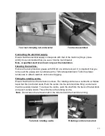
Page 15: ...se and re lubricate with a Teflon based lubricant Teflon has fewer tendencies to attract sawdust and cause clogging Fitting the rotating centre Ensure that the bore of the tail stock is clean The rota...

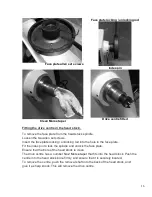
Page 16: ...cking unlocking rod into the hole in the face plate Fit the index pin to lock the spindle and unlock the face plate Ensure that the bore of the head stock is clean The drive centre has a number No 2 M...

Page 17: ...s recommended that the end of the headstock is inline with the end of the bed as this will allow the maximum amount of lathe bed to be used for turning Spindle speed control The lathe has two sets of...

Page 18: ...positions Forward stop reverse When changing spindle direction it is very important that the switch is left in the stop 0 position until the spindle has come to a complete stop If the switch is moved...

Page 19: ...e failure 7 To STOP your lathe ONLY use the forward R off O reverse R switch Never use the speed controller to stop the lathe DO NOT use the speed controller to zero for stopping as this will strain t...

Page 20: ...ons Tapped holes Index pin Untapped hole By utilizing different tapped holes and the spindle holes 16 fixed indexing positions can be achieved Tailstock Fit the handle as shown The tail stock can be m...

Page 21: ...a Teflon based lubricant Troubleshooting The lathe will not start 1 Check that the rotation switch is not in the 0 position 2 Check that the electrical power cord is plugged into the power outlet 3 Ch...

Page 22: ...y motor cooling fins clogged over feeding the job and excessive ambient temperature Squeaking noise 1 Check the bearings 2 Check the drive belt Spindle slows down during a cut 1 Dull cutting tools Rep...

Page 23: ...23...

Page 24: ...24...

Page 25: ...25...

Page 26: ...70 SCREW M4x8 2 21 HANDLE 1 71 BRACKET 4 22 HANDLE WHEEL 1 72 DIGITAL READER 1 23 TAILSTOCK 1 73 HEX NUT M18 1 24 PIN 5X50 1 74 CLAMP 1 C RING C 19 2 75 CLAMP BOLT 1 26 CLAMP BOLT 2 76 BUSHING 2 27 B...

Page 27: ...27 48 WASHER 4 6 98 49 INVERTER COVER 1 WASHER 5 2...

Page 28: ...ations subject to change Machines may be shown with optional accessories 2018 Laguna Tools Inc LAGUNA and the LAGUNA Logo are the registered trademarks of Laguna Tools Inc All rights reserved 2072 Alt...

Reviews: