56
9. Appendix
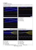
9.1 Reference Waveform
. Below are some waveform charts to show normal UPS operation. It
’s a very useful reference to verify
the test result in section 8.
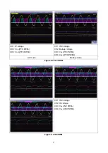
CH1: IP SCR driver
CH2: IP voltage
CH3: -BUS voltage
CH4: +BUS voltage
Figure 9.1 Switch on the input breaker without turn on
CH1: INV voltage
CH2: IP voltage
CH3: -BUS voltage
CH4: +BUS voltage
CH1: INV voltage
CH2: Battery voltage
CH3: -BUS voltage
CH4: +BUS voltage
AC mode (transfer from Bypass mode)
Battery mode
Figure 9.2 Turn on the UPS
Summary of Contents for G31 10K
Page 37: ...37 ...

