INSTRUCTIONS FOR THE INSTALLER
9
2.
2.3.6.
Connection to the flue
The appliance must be connected to the
chimney flue using special piping designed
to resist the products of combustion (e.g.
stainless steel, enamelled steel, etc.).
To connect the flue to the socket flange,
insert the piping inside the flange and seal
the joint with fire sealant or fire cement to
make it completely airtight.
The installer must ensure that the pipe
connected to the appliance is well secured
and there is no chance of it coming free
from its housing (e.g. as a result of
dilatation due to temperature, etc.).
If you have a cast-iron top surface with
a flue socket on top, the flue can be fitted
either on top or at the rear of the
appliance.
In order to fit the flue socket at the rear
of the appliance, remove parts A and B,
and secure flue socket flange D with two
nuts and bolts. Fit cast-iron cover C on the
top surface.
A
B
C
D
Figure No.6 -
Diagram for rear flue socket
In order to fit the flue socket on top of
the appliance, leave parts A and B where
they are (factory position), and secure flue
socket flange D on the top surface with two
nuts and bolts.
A
D
Figure No.7 -
Diagram for top flue socket
2.4.
Chimney flue
The chimney flue must comply with
present standards on the installation of
chimneys.
In rooms equipped with Controlled
Mechanical Ventilation, the ventilation
outlet must never be connected to the
flue.
The appliance must always have its own
chimney flue, never sharing a chimney flue
with another appliance.
2.4.1.
Type of flue
The flue must be made of special
material designed to resist the products of
combustion (e.g. stainless steel, enamelled
steel, etc.).
Non-central-heating
appliances
(without back boiler) require an insulated,
double-sleeve flue only on those sections
that run outdoors or through cold areas.
Single piping can be used inside the
building, the heat of the gases serving to
heat rooms, insulating only those sections
where excess temperature may cause
damage.
If the chimney is constructed, then it is
necessary to pipe and insulate it to ensure
correct updraught.
The diameter of the pipe must be the
same as the diameter of the flue socket on
Summary of Contents for Clasica 5T
Page 1: ...Clásica 5T Clásica 7T Clásica 8T Instruction Book ...
Page 6: ...PRESENTATION OF THE APPLIANCE 5 1 Figure No 2 Dimensions of the Clásica 7T appliance in mm ...
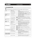
Page 23: ...BASIC BREAKDOWNS 22 6 BASIC BREAKDOWNS Figure No 19 Basic breakdowns ...
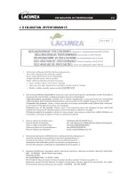
Page 25: ...DECLARATION OF PERFORMANCE 24 7 DECLARATION OF PERFORMANCE ...
Page 26: ...DECLARATION OF PERFORMANCE 25 7 ...
Page 27: ...DECLARATION OF PERFORMANCE 26 7 ...
Page 28: ...DECLARATION OF PERFORMANCE 27 7 ...
Page 29: ...DECLARATION OF PERFORMANCE 28 7 ...
Page 30: ...DECLARATION OF PERFORMANCE 29 7 ...
Page 31: ...CE MARK 30 8 CE MARK ...
Page 32: ...CE MARK 31 8 ...
Page 33: ...CE MARK 32 8 ...
Page 34: ...CE MARK 33 8 ...
Page 35: ...CE MARK 34 8 ...


