background image


INSTRUCTIONS FOR THE INSTALLER 

10 


2.  

the appliance over its entire length in order 
to ensure correct operation. 

The  flue  must  prevent  the  entry  of 

rainwater. 

The flue must be clean and airtight over 

its entire length. 

The flue must be at least 6m tall and the 

chimney  cap  must  not  hinder  the  free 
release of gases.  

If  the  flue  tends  to  suffer  from 

downdraught, then it is necessary to fit an 
effective  anti-downdraught  cowl,  a  static 
cowl or a smoke extraction fan, or reshape 
the chimney.  

Never  make 90º  bends,  except  the  one 

on  kitchen-stove  outlets,  due  to  the  great 
loss of draught they cause, and reduce 45º 
bends down to an absolute minimum. Each 
45º bend is equivalent to a 0.5m reduction 
in  flue  length.  Horizontal  flue  sections 
should  not  be  installed  because  they  cut 
updraught a great deal. 

If the flue draws at more than 20 Pa on 

12Pa  appliances  and  more  than  25Pa  on 
17Pa appliances, then an effective damper 
must be fitted on the flueway. This damper 
must be visible and accessible. 

The  chimney  flue  must  not  rest  on  the 

appliance. 

Bear  in  mind  that  high  temperatures 

may be reached in the flue, meaning that it 
is  essential  that  insulation  be  enhanced  in 
sections  in  which  combustible  material  is 
present (wooden beams, furniture, etc.). It 
may  even  be  necessary  to  protect  non-
combustible  material  in  order  to  prevent 
breakage,  deformation,  etc.,  as  a  result  of 
overheating if the material is not designed 
to withstand high temperatures.  

It  must  be  possible  to  clean  the  entire 

flue, no sections being left inaccessible for 
cleaning purposes. 

2.4.2.


Chimney crown 

The  upper  end  of  the  chimney  must 

clear  the  roof,  the  roof  ridge  or  any 
obstacle located on the roof by at least 1m. 


Figure No.8 -


Distances between chimney 

crown and roof ridge 

Summary of Contents for Clasica 5T

Page 1: ...Clásica 5T Clásica 7T Clásica 8T Instruction Book ...

Page 2: ...stallers 7 2 2 Room for installation 7 2 2 1 Ventilation of the room 7 2 2 2 Location of the appliance in the room 8 2 3 Installation of the appliance 8 2 3 1 Floor 8 2 3 2 Safety distances 8 2 3 3 Checks before lighting for the first time 8 2 3 4 Height adjustment and levelling the appliance 8 2 3 5 Casing 8 2 3 6 Connection to the flue 9 2 4 Chimney flue 9 2 4 1 Type of flue 9 2 4 2 Chimney crow...

Page 3: ...3 Firebox 18 4 1 4 Inside the appliance 18 4 1 5 Flue socket 18 4 1 6 Chrome parts 19 4 1 7 Brass parts 19 4 1 8 Enamelled steel parts 20 4 1 9 Oven 20 4 2 Maintenance of the chimney flue 20 4 3 Important advice 20 TROUBLESHOOTING 21 BASIC BREAKDOWNS 22 DECLARATION OF PERFORMANCE 24 CE MARK 30 ...

Page 4: ...nit Clásica 5T Clásica 7T Clásica 8T Nominal Heat Output N H O to atmosphere kW 9 10 12 5 Efficiency at N H O 78 76 75 CO emission at 13 O2 at N H O 0 04 0 08 0 11 Gas mass flow at N H O g s 11 14 5 13 3 Gas temperature downstream of flue socket at N H O ºC 275 268 330 Optimum flue draught Pa 12 12 12 Wood consumption beech at N H O kg h 2 8 3 2 4 3 Dimensions of the firebox Width mm 200 278 278 D...

Page 5: ...f the fuel fuel loads fuel load frequencies flue draught and system of installation indicated in this Instruction Book Failure to respect these conditions may lead to problems with the appliance deterioration shorter useful life etc which are not covered by the Lacunza warranty Figure No 1 Dimensions of the Clásica 5T appliance in mm ...

Page 6: ...PRESENTATION OF THE APPLIANCE 5 1 Figure No 2 Dimensions of the Clásica 7T appliance in mm ...

Page 7: ...PRESENTATION OF THE APPLIANCE 6 1 Clas ica Figure No 3 Dimensions of the Clásica 8T appliance in mm ...

Page 8: ...olutely crucial to ensure the suitable renewal of the air in the room in which the appliance is fitted the room must always have at least two permanent grilles or openings to the exterior in order to renew the air one for intake and the other for extraction For the installation of its appliances Lacunza recommends an additional section for these openings One of these two grilles must be situated h...

Page 9: ...e material is not designed to withstand high temperatures 2 3 3 Checks before lighting for the first time Make sure that the glass es is are not broken or damaged Make sure that the flueway is not obstructed with packing or loose parts Make sure that the airtight joints on the flue circuit are in perfect condition Make sure that the doors close properly Make sure that all moving parts are fitted i...

Page 10: ...ket on top of the appliance leave parts A and B where they are factory position and secure flue socket flange D on the top surface with two nuts and bolts A D Figure No 7 Diagram for top flue socket 2 4 Chimney flue The chimney flue must comply with present standards on the installation of chimneys In rooms equipped with Controlled Mechanical Ventilation the ventilation outlet must never be connec...

Page 11: ... cut updraught a great deal If the flue draws at more than 20 Pa on 12Pa appliances and more than 25Pa on 17Pa appliances then an effective damper must be fitted on the flueway This damper must be visible and accessible The chimney flue must not rest on the appliance Bear in mind that high temperatures may be reached in the flue meaning that it is essential that insulation be enhanced in sections ...

Page 12: ...ius of the chimney outlet by more than 1m Figure No 9 Distances between the chimney crown and objects within a 10m radius The chimney crown must clear any neighbouring building or obstacle located within a radius of 10m to 20m from the chimney outlet Figure No 10 Distances between the chimney crown and objects within a radius of between 10 and 20m ...

Page 13: ...ely chopped wood produces greater heat output but also burns more quickly Optimum fuels Beech Other fuels Oak chestnut ash maple birch elm etc Pine and eucalyptus logs are low density and produce very long flames and may cause the parts of the appliance to wear out more quickly than normal Resinous wood may mean that the appliance and the flue need to be cleaned more often Non permitted fuels All ...

Page 14: ... No 12 Operating components on the appliance A Firebox door handle B Oven door handle C Direct draught rod o C1 open o C2 closed D Oven thermometer E Primary air intake o E1 open turn clockwise o E2 closed turn anti clockwise F Secondary air intake o F1 open turn clockwise o F2 closed turn anti clockwise ...

Page 15: ...on will no longer appear when the appliance has been lit three or four times and has adapted to its flue If it does not disappear then check the flue draught length and diameter of the flue flue insulation airtightness and the humidity of the wood used If the condensation comes into contact with the enamel wipe it off and dry with a cloth straight away to prevent any possible loss of shine 3 4 Loa...

Page 16: ...open all the air intakes to the firebox and in order to obtain minimum output tend towards closing them For normal use we recommend you close the Primary Intake and leave the Secondary Combustion Intakes open 3 6 Removing ash Following sustained use of the appliance it is necessary to remove the ash from the firebox Remove the ashpit box when cold or using something to prevent yourself from gettin...

Page 17: ...ic or pour sugar on the surface they may become permanently incrusted in the glass Earthenware pots will scratch the glass If you lift the glass you will discover enamelled cast iron protective supports You can cook on top of these but bear in mind the indications given in the Maintenance section How to lift lower the glass ceramic top surface In order to lift the glass ceramic surface and cook on...

Page 18: ... top surface back to its original position repeat the process in reverse order Move gently at all times When you have finished using the protective supports Lacunza recommends that you always return the glass ceramic top surface to its original position horizontal The glass ceramic top surface must always be lifted lowered when cold ...

Page 19: ...ble on the market Enamelled protection Maintain according to the instructions given for Visible enamelled parts front of the kitchen stove Due to their position and function however these parts are subject to a great deal of wear and it is practically impossible to keep them in a good state Cast iron top surface Use special sandpaper and specific products to clean and maintain 4 1 3 Firebox Clean ...

Page 20: ...liance is cold When the flue socket has been cleaned gather up the soot accumulated at the bottom of the oven and extract it via the hatch located beneath the oven Figure No 18 Accesses via which to clean the flue socket 4 1 6 Chrome parts Use a damp cloth with neutral soap to clean the chrome parts and dry immediately Do not use scouring pads abrasive products stripper or acid based products they...

Page 21: ...kitchen stove they may damage the enamel coating 4 2 Maintenance of the chimney flue VERY IMPORTANT In order to avoid incidents chimney fires etc it is necessary to perform maintenance and cleaning operations on a regular basis if the appliance is used often then the chimney and the flue connector piping must be swept several times a year In the event of fire in the chimney close the flue draught ...

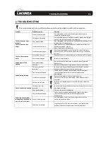
Page 22: ... continually burn chips carpentry scraps plywood pallets etc Cold flue Heat up the flue by burning a piece of paper in the firebox Smoke during burning The room is at low pressure In rooms with Controlled Mechanical Ventilation leave an outdoor window ajar until the fire is fully alight Too little wood loaded Load as recommended Loads notably smaller than those recommended lead to low smoke temper...

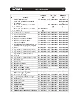
Page 23: ...BASIC BREAKDOWNS 22 6 BASIC BREAKDOWNS Figure No 19 Basic breakdowns ...

Page 24: ...barra Izdo Laton 501000000866 501000000866 501000000866 10 Soporte Sujección barra Dcho Cromado 501000000869 501000000869 501000000869 10 Soporte Sujección barra Dcho Latón 501000000867 501000000867 501000000867 11 Barra Cromada 500000000050 501220000001 500000000024 11 Barra Latón 508020000001 508060000001 508070000001 12 Bandeja esmaltada 501000000002 501000000002 500000000045 13 Bandeja varilla...

Page 25: ...DECLARATION OF PERFORMANCE 24 7 DECLARATION OF PERFORMANCE ...

Page 26: ...DECLARATION OF PERFORMANCE 25 7 ...

Page 27: ...DECLARATION OF PERFORMANCE 26 7 ...

Page 28: ...DECLARATION OF PERFORMANCE 27 7 ...

Page 29: ...DECLARATION OF PERFORMANCE 28 7 ...

Page 30: ...DECLARATION OF PERFORMANCE 29 7 ...

Page 31: ...CE MARK 30 8 CE MARK ...

Page 32: ...CE MARK 31 8 ...

Page 33: ...CE MARK 32 8 ...

Page 34: ...CE MARK 33 8 ...

Page 35: ...CE MARK 34 8 ...

Page 36: ...CE MARK 35 8 LACUNZA KALOR GROUP S A L Pol Ind Ibarrea s n 31800 Alsasua Navarra Spain Tel 00 34 948 56 35 11 Fax 00 34 948 56 35 05 e mail comercial lacunza net Website www lacunza net EDITION 3 ...

Reviews: