background image


6.


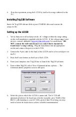
Run the experiment, using the LC220 by itself or leaving it tethered to the 
PC.  

Installing Trig220 Software 

Insert the Trig220 Software disk in your CD-ROM drive and execute the 
setup.exe file. 

Setting up the LC220 

1.


Verify that your wall socket provides AC voltages within the range setting 
on the wall transformer supplied with the LC220.  If the voltage range is not 
correct, contact LabSmith (

[email protected]

) for an alternate.  

DO 

NOT connect the wall transformer to a socket that is beyond the 
transformer’s range setting.

  Plug the transformer into an appropriate 

socket and connect the power to the LC220.  

2.


Connect the 9-pin cable to the back of the LC220 and to a free serial port on 
the PC.  

3.


Press the Power button on the front of the LC220.  

4.


From your computer, run Trig220.exe to launch the Trig220 software. 

5.


From within Trig220, select View>Communications options…. The 
Communications properties screen will open. 


6.


Select the port to which the LC220 is connected. The LC220 will 
automatically detect the baud rate, which is typically set to 38400. If the 
RS232 cable running to your LC220 is greater than 30 m long, you may 
need to lower the baud rate to achieve reliable communication. 

Summary of Contents for LC220

Page 1: ... LC220 Logic Controller User Guide Documentation for the LC220 Controller and Trig220 Control Software v 1 0 ...

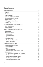
Page 2: ...IG220 SOFTWARE INTERFACE 9 Main screen 9 Time base settings 11 Clock source 11 Clock multiplier 11 Time base 12 General options 12 Disable enable outputs 12 Lock unlock panel 12 CHANNEL PROPERTIES 13 Channel properties screen 13 Quiescent states 14 Logic 14 Logic assignments 15 Experimenting With Channel Logic 16 Timing modes 17 Apply versus Program All Channels 18 Fixed output mode 19 Passive mod...

Page 3: ...ons 27 Validated trigger input mode noise suppression 28 Timer mode 30 Dynamically delayed pulse mode 31 Toggled output mode 36 RUNNING EXPERIMENTS 37 Storing and recalling experiment files 37 Panel controls and indicators 37 GLOSSARY 41 ...

Page 4: ...s Trig220 software and the LC220 logic and timing controller Trig220 lets you configure and run experiments from a simple graphical interface The LC220 controller provides the connections and control for your experimental devices Parts list Your LC220 package should include the following items 1 LC220 controller 2 AC wall transformer 3 Trig220 software installation CD with user s manual 4 9 pin RS...

Page 5: ...are aligned to a time base derived from an internal or external clock allowing resolution down to 5 ns Each channel also includes logic settings which specify the conditions that will trigger the channel A channel can be triggered by logical combinations of signals from the inputs and or the output of the other channel All settings and setting profiles for a particular experiment can be stored as ...

Page 6: ...d the transformer s range setting Plug the transformer into an appropriate socket and connect the power to the LC220 2 Connect the 9 pin cable to the back of the LC220 and to a free serial port on the PC 3 Press the Power button on the front of the LC220 4 From your computer run Trig220 exe to launch the Trig220 software 5 From within Trig220 select View Communications options The Communications p...

Page 7: ...e guide is also available in an Abobe Acrobat Portable Document Format pdf file for electronic viewing Check the LabSmith web site www labsmith com for helpful applications notes and other technical information to help you use the LC220 If you are unable to find the information you need please contact our technical support team at 925 292 5161 or e mail us at info labsmith com If you need to conta...

Page 8: ...he LC220 from the computer or you can run it in stand alone mode Indicators and controls on the LC220 will help you run your experiments You ll learn all about these functions in the Experimenting section later For now we ll give you a short tour of the inputs outputs and controls so you can work with the unit while you learn to use the Trig220 software LED Indicators Channel A Channel B Outputs I...

Page 9: ...ubles as an input jack for an optional external clock source The input and output voltages conform to the TTL standards Panel controls There are three buttons on the LC220 Trigger A and trigger B respectively force channels A and B to be triggered The effect this has on the channels depends on the timing mode of the channels The third button Reset causes both channels to have their timing modes re...

Page 10: ...ies for the experiment Main screen When you run Trig220 you ll be greeted by the Main screen NOTE At start up the Main screen will show the default program which sets both channel outputs to a fixed low state From this screen you ll control or access all of Trig220 s functions Most Trig220 functions can be accessed in two ways by selecting an option from a pull down menu or by pressing a button on...

Page 11: ...ll settings button updates the LC220 with all current settings The Online Offline button toggles between Online and Offline mode In Online mode this button is depressed the Com port is open and settings are transferred to the LC220 In Offline mode this button is not depressed the Com port is available for other programs and settings are not transferred to the LC220 Offline mode is convenient for d...

Page 12: ...lock source The LC220 can derive its time base from an internal 25 MHz oscillator or from a TTL pulse train provided to In1 If the time base is derived from the external input you must specify the frequency of this time base so that Trig220 can set the LC220 timing correctly If the clock frequency specified is 10 higher than actual the channels using this time base will be 10 long on delays and du...

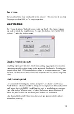
Page 13: ... actions of the channels Enabling the outputs allows the LC220 to send trigger pulses to its output connectors These functions are nonvolatile the enabled and disabled states are restored on power cycle Lock unlock panel Lock or unlock the front panel buttons using the Lock Panel and Unlock Panel buttons This functionality is handy for example in an embedded control application where the LC220 sho...

Page 14: ...establish the logic that will determine when the channel will trigger Channel properties are organized by tabs The tabs that are relevant for a particular timing mode appear automatically when that timing mode is selected For convenience all settings are retained and saved including those for timing modes that are not currently selected Four additional buttons appear next to the tabs ...

Page 15: ...ts You can also force trigger a channel from the LC220 panel See Running Experiments Force Trigger Quiescent states When you disable a channel its input will not change the output The quiescent state of a channel is the setting of its output when the channel is disabled You can set each channel s quiescent state to be a TTL high 3 5 5 V or low 0 0 2 V to provide a safe signal to the output device ...

Page 16: ... The logic processor assigns the logical combination of external inputs In1 and In2 and other channel output that will trigger each channel Logic assignments have the following format the channel to be triggered the conditions that will trigger it Here is an example InB In2 This assignment means Channel B will be triggered when the signal on In2 goes TRUE reaches 5 V ...

Page 17: ... FALSE Experimenting With Channel Logic This brief example will show you more about channel logic 1 Connect a normally open switch to In1 and another to In2 2 Connect an LED to OutA 3 Choose Output Input from the Timing mode list for Channel A In this mode the output of Channel A is always the same as its input 4 Select the Passive tab and choose Output Input 5 Select the Logic tab and select inA ...

Page 18: ... to InA Not In2 10 Click the Program All Settings button The LED at Output A will remain off until you close Switch 2 11 Lastly change the logic assignment to InA Not In1 And Not In2 12 Click the Program All Channels button The LED at Output A will remain off until both switches are closed Timing modes In the previous section you learned that logic defines how channels are triggered In this sectio...

Page 19: ...is connected to the PC 2 Plug a normally open push button trigger switch into In1 The button will represent our triggering event 3 Open Channel A s Setting screen and select the Statically delayed pulse timing mode you ll learn about Statically delayed pulse mode shortly 4 Select the Logic tab and select the logical assignment InA Not In1 Then click Apply With this logic Channel A will trigger whe...

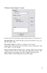
Page 20: ...d state Low or High regardless of the input The panel LED for the channel will glow green when the output is low or red when the output is high To try fixed output mode On the Properties tab of Channel A choose Fixed Output Choose Low or High as the output state then click Apply to save the settings At Output A the signal will remain a steady TTL logic low or high depending on your selection ...

Page 21: ...On Channel A s Settings screen select the Output Input timing mode In the Function box choose Output Input then Click Apply to save the settings When the trigger button is not depressed i e the input signal is low the signal at Output A will be a TTL low Now depress the trigger button at Input 1 the signal at Output A will go high If you select Output Input invert the channel output will remain hi...

Page 22: ... For a high frequency clock the LED will alternate between red and green so quickly that it will appear as a continuous pale green yellow or orange light As mentioned earlier the LC220 can operate with different time bases see Time Base Settings With a 5 ns time base internal clock X 8 the clock pulse and duration can range from 0 48 µs to 52 4 ms At longer time bases this range is proportionally ...

Page 23: ...iescent state for the channel should be high instead To try Clock mode 1 On the Time base settings screen select internal clock and a clock multiplier of 1 8 X 2 On Channel A s Properties tab choose Clock as the mode select an on duration of 100 ms and an off duration of 500 ms Click Apply to save the settings The signal at Output A will go repeatedly go high for 100 ms then go low for 500 ms Stat...

Page 24: ...will remain high after a valid trigger until the channel is reset Inverted Output Check the box to set the output high until a valid trigger The range of settings you can use with the delayed trigger depend upon the current timing mode Time base 5 ns 320 ns Delay range 20 ns to 21 47 s 1 28 µs to 1374 s Duration range 7 7 µs to 21 47 s 493 µs to 1374 s Delay Duration resolution 5 ns 320 ns ...

Page 25: ...number of retriggers allowed between resets between 0 and 2 147 483 647 To allow a channel to be triggered again after reaching the limit the channel must be reset To reset both channels press the Reset button on the LC220 or choose Actions Reset in Trig220 To reset only one channel click the Reset button next to the channel settings Trigger on rising input Sets the channel to be edge triggered In...

Page 26: ...ng high precision Sweep To facilitate time delay scanning experiments the delay of the pulse relative to the trigger can be swept or incremented by a specified value each time the channel is triggered The sweep value must be positive The increment resolution is equal to the time base e g as short as 5 ns The panel LED for the delayed trigger will glow green until an input signal is detected The LE...

Page 27: ...retrigger the channel Click the Reset button on the LC220 the LED glows green and you can once again trigger the channel 7 On the Triggering tab choose Retrigger N times set N 5 then click Apply Depress and hold the trigger button As long as the trigger is depressed i e the input signal is high the channel will continue to trigger until the limit is reached 8 Again on the Triggering tab select Ris...

Page 28: ...ts For example in the diagram below two trigger pulses arrive 100 μs apart The channel is functioning in Statically delayed pulse mode with a delay of 50 μs and a duration of 45 μs pulse It would receive the first pulse wait 50 μs send a 45 μs output pulse and trigger again at the second pulse But the extra 10 μs delay at the end of the sequence will cause the channel to ignore the second trigger ...

Page 29: ...pulse of user specified duration will be sent to the channel output Unlike an analog filter which smears the signal edge this noise suppression function digitally blocks false triggers retaining the sharp edges on the real trigger signal As with Statically delayed pulse mode you have additional controls over the channel On the Validate tab choose Minimum duration The minimum length of an input pul...

Page 30: ... on the LC220 or choose Actions Reset in Trig220 To reset only one channel click the Reset button next to the channel settings Trigger on input high While the input is high channel can be repeatedly triggered Trigger on rising input Sets the channel to be edge triggered i e an input signal that stays high will only trigger the channel once The panel LED for the noise suppression channel will glow ...

Page 31: ...N times and set N 50 Click Apply to save the settings 5 Now depress the trigger button If you hold the button down for more than one second the minimum duration the output of Channel A will go high If you release the button before one second elapses the output will remain low and the channel will wait for another input pulse Timer mode The counter timer mode determines the time delay between two s...

Page 32: ...nters are initially disabled and must be enabled either by clicking the Enable button on the channel s Properties screen or by using the front panel See Experimenting Disable Enable Channels below The panel LED for the timer will be green until the first trigger red until the second trigger and off while the count data is reported and the channel waits for the input to return low The output of a c...

Page 33: ...lly delayed pulse mode includes several properties tabs Scaling In the calculation of the delay the measured delay between two pulses is scaled by a factor of 2N where 16 N 16 or N 16 where 0 N 256 The former scaling is faster and a scaling of 1 1 is fastest Scaling can typically be done at rates 50 kHz at a 5 ns time base The maximum delay between input pulses is 52 ms at a time base of 5 ns and ...

Page 34: ...ns the delay time and the resolution is set by the time base e g 10 ns Duration of pulse The duration of the output signal Until Reset The output will remain high after a trigger until the channel is reset Inverted Output Check to set the output high until a valid trigger The duration of the pulse and other properties are the same as for the delayed trigger Triggering The triggering options are th...

Page 35: ...til the output signal is sent At this point the LED will return to green if retriggering is allowed or it will glow red to indicate that no more input signals will be accepted To try the dynamically delayed pulse mode You can simulate the experiment above using the trigger button to represent Sensor 1 and a delayed trigger in Channel B to represent the signal from Sensor 2 Connect your oscilloscop...

Page 36: ...ger button quickly Channel A will produce a trigger pulse 500 ms later Both the button push and delayed signal will appear on the inputs of Channel B When Channel B receives the button push signal it will begin its count When Channel B receives the delayed pulse from Channel A it will calculate the time difference 500 ms multiply it by 32 16 and subtract the 200 µs offset 999 8 ms after receiving ...

Page 37: ...l for a variety of logical and control purposes The minimum input pulse state duration is 10 ns and the edge to toggle delay is 20 ns The only user settings for this mode are the initial state which may be either low or high The panel LED for the channel will glow green when the output is low or red when the output is high ...

Page 38: ...ttings to download the settings to the LC220 NOTE Good file naming protocol will help your experiments go more smoothly For example if you are saving multiple versions of a combustion experiment store all files in the same directory with the names combustion1 trg combustion2 tr2 etc Or better yet use descriptive names such as combust 50us delay tr2 combust 60us delay tr2 etc Panel controls and ind...

Page 39: ...nel is in the process of triggering When a channel is in Fixed output Clocked pulse stream Output Input or Toggled output timing modes the red light indicates that the output is currently HIGH for that channel 3 When a channel indicator is steadily off the channel is disabled see Enable Disable Channels below The channel indicator also turns off during delays and while waiting for the input to ret...

Page 40: ...igger if retriggering is on light will glow green once input goes low In duration period if retriggering is off light remains red after duration period Timer Timer data is being reported waiting for input to go low Waiting for first trigger pulse Waiting for second trigger pulse Dynamically delayed pulse Waiting for trigger if retriggering is on light will glow green once input goes low In duratio...

Page 41: ...channel regardless of the channel s logic settings or state This is a useful way to initiate a timing sequence without actually performing the live experiment You can also trigger a channel from within the Trig220 software See Channel Properties Force Trigger above Reset The Reset button returns both channels to the last programmed settings It resets and reinitializes retriggering counters and the...

Page 42: ...The LC220 hardware unit Counter timer mode This timing mode determines the time delay between two separate input signals Delay The time between the arrival of an input trigger and the release of an output pulse Duration The length of an output pulse Dynamically delayed pulse Timing mode measures the time difference between two pulses scales that difference by a user defined factor waits the durati...

Page 43: ...lse triggers due to noise on the input signal by requiring the signal to remain high or low for a specified duration Output One of two output jacks on the LC220 The output signals are determined by the timing channels Program all settings A function which sends all logic and timing settings to the LC220 Programmable logic controller A device which combines logic and timing processors for precise c...

Page 44: ...ase The minimum increment of time used by the LC220 This can range from 5 ns to 1000 ns and can be generated from an internal or external clock Timer Counter Timer mode determines the time delay between two separate input signals and reports it back to the PC Timing mode The eight functions that each channel can perform Toggle mode Toggles its output state upon every input pulse Trigger An input s...

Page 45: ...ent of LabSmith To Our Valued Customers User s Manual and Trig220 Control Software To obtain the most up to date version of this user s manual and Trig220 Control Software please refer to our website at http www labsmith com Corrections to this user s manual and Trig220 Control Software Please contact support labsmith com to report any information that is missing or in error in this user s manual ...

Reviews: