18
-
Dynamically delayed pulse
-
Timer
-
Toggled output.
When a timing mode is selected, the relevant property tabs will be displayed.
NOTE:
All timing property tabs include a space for Notes. These notes
are saved and appear in the Main Screen program summary area. It is
good practice to document your settings extensively. As with all
programming, good documentation will simplify the process of
creating, debugging and running your experiments.
For each timing mode you’ll be able to set up a simple example to view the
output of the channel.
To set up for the experiments later in this section
:
1.
Make sure that the LC220 is connected to the PC.
2.
Plug a normally open push-button trigger switch into In1. The button will
represent our triggering “event.”
3.
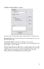
Open Channel A’s Setting screen, and select the “Statically delayed
pulse” timing mode (you’ll learn about Statically delayed pulse mode
shortly).
4.
Select the “Logic” tab and select the logical assignment:
InA = Not In1.
Then click Apply. With this logic, Channel A will trigger when you
depress the trigger button.
5.
Plug an oscilloscope to Output A to observe the channel output.
Remember, the output voltage will vary from 0 to 5 V.
“Apply” versus “Program All Channels”
Each properties screen includes an “Apply” button which, when clicked, will
send the current timing properties to the channel on the LC220. The other
channel function, for example retriggering counters and triggering, is not
affected.


