background image

MRX Multi-kit Demolition Tool Operation & Maintenance Manual | 23

INSPECT / TORQUE BOLTS

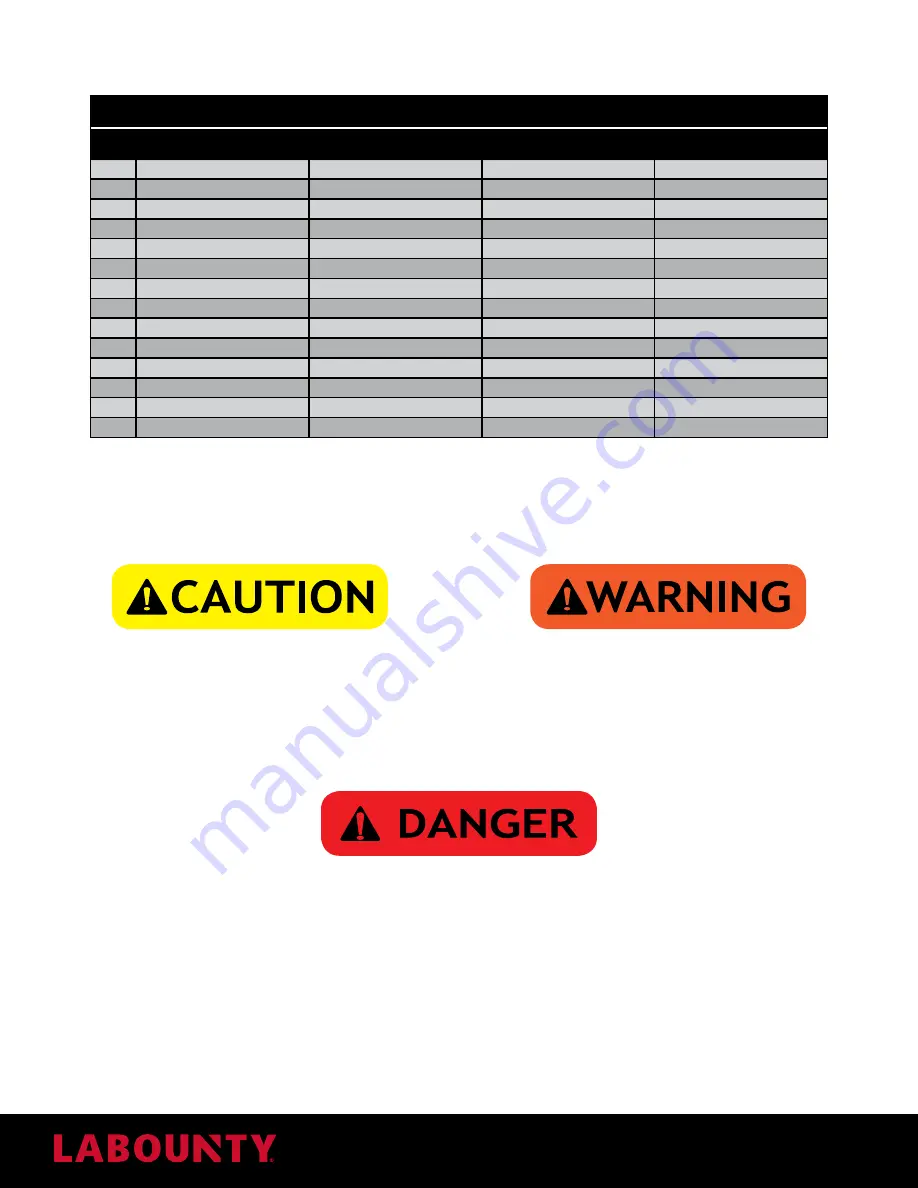
General Fastener Torque Table

Size

6S

8.8 - (8G)

Class 10.9

Class 12.9

M5

4 Ft. Lbs. (5.10 Nm)

4 Ft. Lbs. (5.98 Nm)

6 Ft. Lbs. (8.5 Nm)

8 Ft. Lbs. (10.2 Nm)

M6

6 Ft. Lbs. (8.73 Nm)

8 Ft. Lbs. (10.3 Nm)

11 Ft. Lbs. (14.7 Nm)

13 Ft. Lbs. (17.6 Nm)

M8

16 Ft. Lbs. (21.58 Nm)

19 Ft. Lbs. (25.5 Nm)

26 Ft. Lbs. (35.3 Nm)

31 Ft. Lbs. (42 Nm)

M10

31 Ft. Lbs. (42.2 Nm)

37 Ft. Lbs. (50 Nm)

52 Ft. Lbs. (70.6 Nm)

63 Ft. Lbs. (85.5 Nm)

M12

54 Ft. Lbs. (73.6 Nm)

64 Ft. Lbs. (87.3 Nm)

90 Ft. Lbs. (122.6 Nm)

108 Ft. Lbs. (147 Nm)

M14

86 Ft. Lbs. (116.7Nm)

102 Ft. Lbs. (138.3 Nm)

143 Ft. Lbs. (194.2 Nm)

174 Ft. Lbs. (235.5 Nm)

M16

132 Ft. Lbs. (178.5 Nm)

156 Ft. Lbs. (210.9 Nm)

221 Ft. Lbs. (299.2 Nm)

264 Ft. Lbs. (358 Nm)

M18

181 Ft. Lbs. (245 Nm)

213 Ft. Lbs. (289.4 Nm)

304 Ft. Lbs. (412 Nm)

362 Ft. Lbs. (490.5 Nm)

M20

257 Ft. Lbs. (348.5 Nm)

304 Ft. Lbs. (412 Nm)

427 Ft. Lbs. (578.8 Nm)

514 Ft. Lbs. (696.5 Nm)

M22

347 Ft. Lbs. (471 Nm)

412 Ft. Lbs. (559.2 Nm)

579 Ft. Lbs. (784.8 Nm)

695 Ft. Lbs. (942 Nm)

M24

441 Ft. Lbs. (598.5 Nm)

525 Ft. Lbs. (711.2 Nm)

738 Ft. Lbs. (1000.5 Nm)

883 Ft. Lbs. (1197 Nm)

M27

655 Ft. Lbs. (888 Nm)

774 Ft. Lbs. (1049.7 Nm)

1092 Ft. Lbs. (1481 Nm)

1310 Ft. Lbs. (1776 Nm)

M30

890 Ft. Lbs. (1206.5 Nm)

1049 Ft. Lbs. (1422.4 Nm)

1483 Ft. Lbs. (2011 Nm)

1772 Ft. Lbs. (2403 Nm)

M33

1201 Ft. Lbs. (1628.5 Nm)

1425 Ft. Lbs. (1932.6 Nm)

2004 Ft. Lbs. (2717 Nm)

2410 Ft. Lbs. (3267 Nm)

BLADE MAINTENANCE

Before performing blade maintenance, place the attachment on the ground, so that the part being maintained is closest 

to the ground. When performing maintenance on the upper jaw curl the attachment under the stick so that the upper 

jaw is on the ground.

Wear personal protection equipment at all times. This 

includes eye protection, hard hat, steel toe shoes, 

leather gloves and hearing protection.

Blades are very heavy. Do not remove a blade if it’s not 

supported. The blade may fall and cause injury.

CRACKER JAW

Measuring Blade Gap and Shimming

Note: Removing and handling blades can be hazardous if done incorrectly. 

Stay at least 75 ft. (23 m) when moving.

1. 

Cycle the tool until the upper jaw blade begins to overlap the lower jaw blade.

2. 

Measure the blade gap. If the gap is larger than 0.4 mm, add shims between the guide blade and blade seat until the 

gap is  0.4 mm - 0.4 mm.

Blade Rotation

Each cracker jaw blade has four edges. Each time you rotate the blade, use a different edge until all the edges are 

worn to .25” radius.

Summary of Contents for MRX Series

Page 1: ...N TOOL SAFETY OPERATION MAINTENANCE 519014 User Manual 3 2020 Ver 1 MRX LaBounty 1538 Hwy 2 Two Harbors MN 55616 1 800 522 5059 www stanleyinfrastructure com brands labounty www stanleyinfrastructure...

Page 2: ...ediately contact any authorized LaBounty dealer You may also download a PDF copy at www stanleyinfrastructure com REGISTRATION FORM The Warranty Registration Form must be filled out by the dealer or c...

Page 3: ...hnical Specifications 17 Controls 17 Bleed the Attachment Hydraulic Circuit 17 MAINTENANCE 19 8 Hours Inspection Checklist 19 Daily Inspection Checklist 19 40 Hour Inspection Checklist 20 6 Month Insp...

Page 4: ...ppear throughout the manual along with additional specific rules for safety and operation GENERAL If the attachment is not functioning properly shut down the machine follow proper Lock out Tag out pro...

Page 5: ...with the proper safety guards for LaBounty applications The cab MUST be equipped with an approved Falling Object Protection Structure FOPS and cab guarding The FOPS must meet the requirements of SAE s...

Page 6: ...Tool Operation Maintenance Manual DECALS Servicing while pressurized can cause sever injury LOCK OUT source and RELIEVE PRESSURE before servicing Top and front cab guarding required during any materi...

Page 7: ...condary demolition applications The interchangeable jaws designs facilitate improved penetration and rapid material downsizing TERMS JAW MOUNTING PIN JAW MOUNTING PIN IDENTIFICATION PLATE CYLINDER ROT...

Page 8: ...vertically 3 Remove the excavator bucket Follow the manufacturer s recommended procedure Note Plug hydraulic hoses to prevent contamination 4 Clean the inside surface of the attachment bracket and al...

Page 9: ...rized Escaping fluid under pressure can penetrate the skin causing serious injury Trapped hydraulic pressure may be present after the excavator is shut off Extreme caution must be taken when removing...

Page 10: ...rols one accessed from the rotating head cover and another accessed from the top of the attachment 1 Remove the cover from the rotating head The flow control port will be attached to the port block Tu...

Page 11: ...under the excavator and position it so that it can be accessed from the ground 3 Remove the locking screw from the hydraulic lock using a 5 mm hex wrench 4 Using a 19 mm socket turn the hydraulic lock...

Page 12: ...0 Release the auxiliary circuit control then have a helper quickly turn the hydraulic lock to the closed position If performed correctly the jaw locking pin will be fully extended Fully extended jaw l...

Page 13: ...ers then slowly raise the jaw off of the ground Note The cylinder and the hinged jaw will not be attached The hinged jaw will be free hanging Use caution when moving 13 Knuckle the attachment under th...

Page 14: ...nd the MRX cylinder until the cylinder coupler interfaces with the lower jaw pin 17 Remove the breaker bar and close the cylinder hook around the lower jaw coupling 18 Insert the pin screw and washer...

Page 15: ...re may be present after the base machine is shut off Extreme caution must be taken when removing hydraulic hoses or lines Injury or death could result 5 Remove and plug all hydraulic lines 6 Store the...

Page 16: ...rs in or near the operating area SAFETY DEVICES Seat belts Canopies Safety decals Shields and guards Flags and flares Barricades Signs and other markings Warning lights Falling Objects Protective Stru...

Page 17: ...2 8 m 77 000 Lbs 35 mTons MRX350 Shear 8 780 Lbs 4 000 Kg 20 7 in 530 mm 22 2 in 560 mm 8 8 ft 2 7 m 99 000 Lbs 45 mTons Concrete Pulverizer 9 430 Lbs 4 300 Kg 38 2 in 970 mm 33 9 in 860 mm 9 5 ft 2 9...

Page 18: ...this time 8 Check the base machine hydraulic fluid level and fill if necessary 9 Slowly extend and retract the excavator cylinder to it s limits Check for interference between the attachment and the e...

Page 19: ...___________ DAILY INSPECTION CHECKLIST Visual Inspection _______Ensure the identification plate is present and legible Replace if necessary _______Inspect all tool decals and ensure they are legible R...

Page 20: ...ure the play between the blades Ensure the play is between 0 2 1 2 mm If the play is greater shim the blades see Blade Maintenance on page 23 Inspected By _____________________________________________...

Page 21: ...22 F 266 F 30 C 130 C Cardrexa GR 1 AL 22 F 266 F 30 C 130 C Esso Multi Purpose Grease Moly 22 F 266 F 30 C 130 C Viscum Fluids 14 F 302 F 10 C 150 C Mobiltac 81 22 F 266 F 30 C 130 C Grafloscon C SG...

Page 22: ...22 MRX Multi kit Demolition Tool Operation Maintenance Manual Cracker Jaw Grease Fittings G Pulverizer Jaw Grease Fittings G Shear Jaw Grease Fittings G...

Page 23: ...Nm 1092 Ft Lbs 1481 Nm 1310 Ft Lbs 1776 Nm M30 890 Ft Lbs 1206 5 Nm 1049 Ft Lbs 1422 4 Nm 1483 Ft Lbs 2011 Nm 1772 Ft Lbs 2403 Nm M33 1201 Ft Lbs 1628 5 Nm 1425 Ft Lbs 1932 6 Nm 2004 Ft Lbs 2717 Nm 2...

Page 24: ...lade 2 Measure the blade gap If the gap is larger than 0 4 mm add shims between the guide blade and blade seat until the gap is 0 4 mm 0 4 mm Blade Rotation Each pulverizer jaw blade has two edges Fli...

Page 25: ...If the gap is larger than 0 4 mm remove the guide blade and insert shims until the gap is within 0 4 mm 4 If you are unable to shim the blade within the 0 4 mm gap measurement you must rotate the bla...

Page 26: ...rotated Once worn the blade must be replaced 1 Loosen the blade tip bolts 2 Remove the blade 3 Clean the blade seat 4 Install a new tip blade and replace the blade bolts Torque as specified in Inspect...

Page 27: ...0C Ni1 Hardsurfacing Recommendations Hardsurfacing must be inspected and maintained For hardsurfacing LaBounty recommends FabTuf 960 or equivalent If you have questions about what hardsurface material...

Page 28: ...28 MRX Multi kit Demolition Tool Operation Maintenance Manual Wear Plates...

Page 29: ...MRX Multi kit Demolition Tool Operation Maintenance Manual 29 CRACKER JAW Hard weld areas Wear plates SHEAR JAW Hard wear areas...

Page 30: ...30 MRX Multi kit Demolition Tool Operation Maintenance Manual...

Page 31: ...YDRAULIC DIAGRAM HYDRAULIC POWER DIAGRAM 8 ATTACHMENTS PAR DESCRIPTION 5 Hydraulic diagrams 1 Machine system 2 Flow regulator valve 3 Anti shock valve 4 Orbital hydraulic motor 1 Machine system 2 Rota...

Page 32: ...n must be taken when removing hydraulic hoses or lines Injury or death could result 1 Before performing maintenance place the attachment on flat hard ground so that the part being maintained is closes...

Page 33: ......

Page 34: ......

Page 35: ......

Page 36: ...your dealer or the LaBounty parts department and requesting a CE Operation Maintenance manual You must include the attachment model number and serial number LaBounty 1538 Hwy 2 Two Harbors MN 55616 1...

Reviews: