background image

Edition 3 April 2012   


Mars/Mars Pro Service Manual


Page


5/59 


55 


10.5 Front aperture retention test  


 48 


10.6 Fuse replacement 


 49 

 
11. 

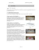
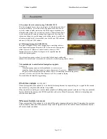
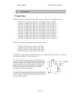
Log Book 


 50 

 
12. 

Decontamination statement  


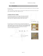
 51 

 
14. 

Wiring diagrams 


 44 

 
15. 

Technical Specification 


55 

 
16. 

Wiring Diagram 


56 

Summary of Contents for Mars

Page 1: ...Edition 3 April 2012 Mars Mars Pro Service Manual Page 1 59 Mars Mars Pro Class 2 Biohazard Safety Cabinet or Cytotoxic Cabinet With automatic control system MICROPROCESSOR BASED...

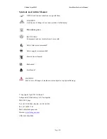
Page 2: ...NG Components and raw materials can be recycled Safety Gloves recommended Safety goggles recommended Electric shock hazard Biohazard Fire Hazard CAUTION Used in case of danger of medium or minor injur...

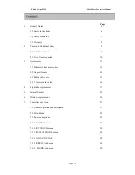
Page 3: ...11 3 1 Exhaust system accessories 11 3 2 Support frames 14 3 3 Media valves etc 15 3 3 1 Gas solenoid valve 16 4 Light tube replacement 17 5 Internal Sockets 25 6 Window replacement 26 7 Controller o...

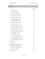
Page 4: ...e menu 35 7 3 5 12 ALARM MODE Service menu 36 7 3 5 13 SERVICE KEY Service menu 37 7 3 5 14 EXT CONTROL Service menu 37 7 3 5 15 EXT ALARM DELAY Service menu 37 7 3 5 16 DECON Service menu 38 7 3 5 17...

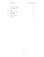
Page 5: ...rs Mars Pro Service Manual Page 5 59 55 10 5 Front aperture retention test 48 10 6 Fuse replacement 49 11 Log Book 50 12 Decontamination statement 51 14 Wiring diagrams 44 15 Technical Specification 5...

Page 6: ...Cabinet can be used for manipulations of Biohazardous and toxic materials so internal components and filters can be contaminated Service personnel must therefore observe strict safety precautions when...

Page 7: ...ate of Decontamination must be produced by the operator before removal from the laboratory NOTE Start up after service repair If any safety devices shielding earthing etc were removed or disabled prio...

Page 8: ...nged without authorization Only original spare parts or accessories as supplied by Labogene are used Use of non original parts will invalidate the warranty Maintenance and service checks are carried o...

Page 9: ...ut additional leverage Sealant For areas requiring sealing with silicone we recommend Sista F 109 or similar Cleaner For surface cleaning of components we recommend commercially available washing agen...

Page 10: ...tools may be required Socket wrench set 6 32mm Slot head screwdriver set 2 6mm Phillips screwdriver set preferably magnetic Open ended wrench set 6 32mm Allen Key set 1 5 6mm Multimeter U I Ohm Diago...

Page 11: ...cabinets and one for 1500 and 1800 cabinets NOTE When fitting or removing the secondary filter take care to avoid damage to the air flow sensor shown in Fig 2 Fig 2 3 Direct duct kit for thimble extra...

Page 12: ...ble for both single and double exhaust filter cabinets and is secured to the cabinet by means of spring clips as shown 7 Formaldehyde neutralization fumigation top plate 9 000 020 115 When fumigating...

Page 13: ...tomatic operation of the cabinet is required The cabinet is run at reduced speed and when the operator starts to work in the cabinet the PIR sensor detects the movement and automatically sets the fans...

Page 14: ...eight of 80 85 cm for Mars1500 9 001 040 014 Adjustable support stand to give work height of 80 85 cm for Mars1800 There is also an electrically adjustable support frame available as follows 9 001 020...

Page 15: ...ows Both side windows are as standard provided with one hole of 23mm for the fitting of such connections If more media connections are required then the window can be replaced with one having 3 holes...

Page 16: ...ormally on connection on Relay 1 on the external PCB Then make a connection from the live output on the 230v input to the COM common connection on Relay 1 Button 6 is then used to turn the gas supply...

Page 17: ...ge Fig 3 3 The fluorescent light tubes can then be seen along the top front and rear of the cabinet work area See Fig 4 4 Ensure the power is turned off and rotate the tube through 90 so 5 the tube is...

Page 18: ...ince the UV effectiveness reduces with time it is recommended that the UV tube be replaced annually if used regularly daily or at a running time of no more than 2000 hours To replace the UV lamp proce...

Page 19: ...Edition 3 April 2012 Mars Mars Pro Service Manual Page 19 59...

Page 20: ...Edition 3 April 2012 Mars Mars Pro Service Manual Page 20 59...

Page 21: ...Edition 3 April 2012 Mars Mars Pro Service Manual Page 21 59...

Page 22: ...Edition 3 April 2012 Mars Mars Pro Service Manual Page 22 59...

Page 23: ...Edition 3 April 2012 Mars Mars Pro Service Manual Page 23 59...

Page 24: ...ro Service Manual Page 24 59 NOTE Always use gloves when handling a germicidal UV lamp to prevent leaving finger prints that will reduce the effects of UV irradiation Replace the lamp every 2000 hours...

Page 25: ...screw the 4 retaining screws securing the socket to the cabinet wall and carefully pull the socket away from the wall Disconnect the wiring from the rear of the socket Replace with a new socket in the...

Page 26: ...ove replace the side window the procedure is as follows from the outside of the cabinet Gently cut away the silicon from around the edge of the outer window frame Pull away the frame casing to expose...

Page 27: ...codes for access to the service mode or for when setting clock time or decontamination times Button identity Button 1 with green LED light used to select the fan ON OFF at normal velocity The green l...

Page 28: ...for scrolling up in sub menus Button 8 for scrolling back to previous heading in sub menu Button 9 for scrolling forward in sub menu Button 10 for lowering window and scrolling down in sub menus Centr...

Page 29: ...selected then press the ENTER button again to accept it If the ENTER button is not pressed with 6 seconds then the display will revert back to normal start menu display 7 3 Sub menu options Each sub m...

Page 30: ...e fans to start up and stop at a pre set time every day Enter and select AUTO or OFF If AUTO is selected then fans will start stop at time selected on sub menu Enter submenu to select full speed or re...

Page 31: ...ations of EN 12469 2000 an anemometer should be used as indicated in the standard to measure the airflow and adjustment should only be carried out if necessary NOTE The down flow speed for the Mars ca...

Page 32: ...risk of turbulence at the front edge Reasons for KI test failure should be investigated before the fan speeds are adjusted as outside influences can greatly affect the airflows Once the speed is adju...

Page 33: ...er the LIGHT MODE and the sub menus are activated The SAFE mode should be selected when no fluorescent light is to be on in the work area when the REDUCED SPEED fan is running in the cabinet or there...

Page 34: ...TER button to access this menu Once accessed the LOW FLOW alarm can be adjusted up or down using the buttons The figure shown is an arbitrary figure and does not indicate a set point in m sec It shoul...

Page 35: ...t in m sec It should be set so that it is higher than the FAN 1 speed setting that is set as per Section 6 3 5 4 The default setting is normally 600 A high flow alarm is not as important for the inflo...

Page 36: ...to normal configuration Press Enter to confirm which will move menu back to SERVICE MODE Sets all alarm settings to Press Enter to accept which will move menu back to SERVICE MODE This has 2 further...

Page 37: ...N REDUCED SPEED for the down flow fan Press ENTER to access the next menu which will allow the setting of alarms for the external signal Once set Press ENTER to confiorm and return back to the service...

Page 38: ...the main menu or select it by pressing ENTER The recommended settings are Formaldehyde evaporation Formaldehyde Dwell time Ammonia Neutralization Ammonia Dwell time Exhaust Airing Press ENTER to sele...

Page 39: ...light is fitted LIGHT ON On Off Put to ON BUZZER ON On Off Put to ON Only select OFF if no audible alarm wanted DOOR SWITCH ON On Off Put to ON for MARS Off for Fortuna LOCK KEY On Off Put to ON 7 3 5...

Page 40: ...cess the menu Once accessed the display will show MIN and the time required before sleep can be input Once the time is input press ENTER to confirm it and return to the main menu By exiting the Servic...

Page 41: ...otor Replacement of window motor 1 Under the 4 screws holding top plate and remove cover 2 Manually raise window and place block under window raising it about 50mm from worktop This loosens belt suppo...

Page 42: ...place new motor back into casing and insert locating screw a new hole may have to be drilled for the screw ensure that it is located opposite where the wires enter the motor 7 Reassemble and then rep...

Page 43: ...Exhaust filter 9 000 050 001 MARS 900 457x915x110 115 mm H 14 457x610x69 mm Cat No 9 000 060 001 9 000 050 002 MARS 1200 457x1220x110 115 mm H14 457x610x69 mm Cat No 9 000 060 001 9 000 050 003 MARS 1...

Page 44: ...tests airflow speed checks and annually a KI Discus test for testing containment Also refer to any local or national standards that may need to be adhered to Refer to Section 10 for more information...

Page 45: ...fans are access from behind the front service panel which must first be removed Ensure the cabinet has been fully decontaminated and that the users can produce a decontamination certificate to ensure...

Page 46: ...e measuring spots on the tabletop are for Mars 1200 GS Min 4 in a line evenly divided 125 mm from the back wall and 4 in another line 200 mm from the front window Each point is to be measured in at le...

Page 47: ...an steady movement along the front opening outside the cabinet The smoke must be drawn into the cabinet without visible turbulence Test the laminarity of the downflow and along the side and back wall...

Page 48: ...n the filter membrane will show up as brown spots The amount of spots is to be counted Acceptance Apf 1 105 Refer to EN 12469 for details Maintenance Every 5000 operating hours or at least once every...

Page 49: ...he fuses of Mars 1200 are located in the right side of the top of the cabinet behind a protective cover Component Fuse Phase zero Main F10 T10A 5x20 Main F6 T10A 5x20 Electrical outlet F3 T6 3A 5x20 E...

Page 50: ...Edition 3 April 2012 Mars Mars Pro Service Manual Page 50 59...

Page 51: ...________________________________________________________________________________ ____________________________________________________________________________________ __________________________________...

Page 52: ...et for Mars 900 and Mars 1200 11 9 001 020 121 Direct duct kit with top exhaust outlet for Mars 1500 and Mars 1800 6 11 9 001 020 116 VHP fumigation program and top plate 7 11 9 001 020 115 Formalin f...

Page 53: ...0 050 003 Main HEPA filter 1500 25 9 000 050 004 Main HEPA filter 1800 26 9 000 060 001 Exhaust HEPA filter 900 1200 27 9 000 060 002 Exhaust HEPA filter 1500 1800 28 9 000 071 001 Laminator 900 29 9...

Page 54: ...1 023 003 Antivibration stand with marble stone 90cm 6 decimal places Mars 1500 46 9 001 023 004 Antivibration stand with marble stone 90cm 6 decimal places Mars 1800 47 9 001 220 131 Sliding Lead win...

Page 55: ...y Voltage frequency V Hz 220 50 Power consumption W 600 Required fusing A Fuse 10 A or circuit breaker 10 A Input current A 1 8 Socket s outlets V Hz A 230 50 4 Max leakage current 1 5 mA Max leakage...

Page 56: ...Edition 3 April 2012 Mars Mars Pro Service Manual Page 56 59...

Page 57: ...Edition 3 April 2012 Mars Mars Pro Service Manual Page 57 59...

Page 58: ...Edition 3 April 2012 Mars Mars Pro Service Manual Page 58 59...

Page 59: ...Edition 3 April 2012 Mars Mars Pro Service Manual Page 59 59...

Reviews: