7
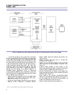
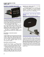
Figure 14. Computer-based control of clutter and interference
generation.
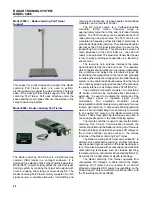
Figure 15. On-line help screens are available through a few clicks
of the mouse button.
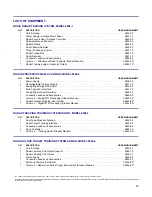
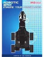
Figure 16. The Radar Tracking Training System, Model 8096-3.
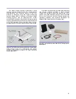
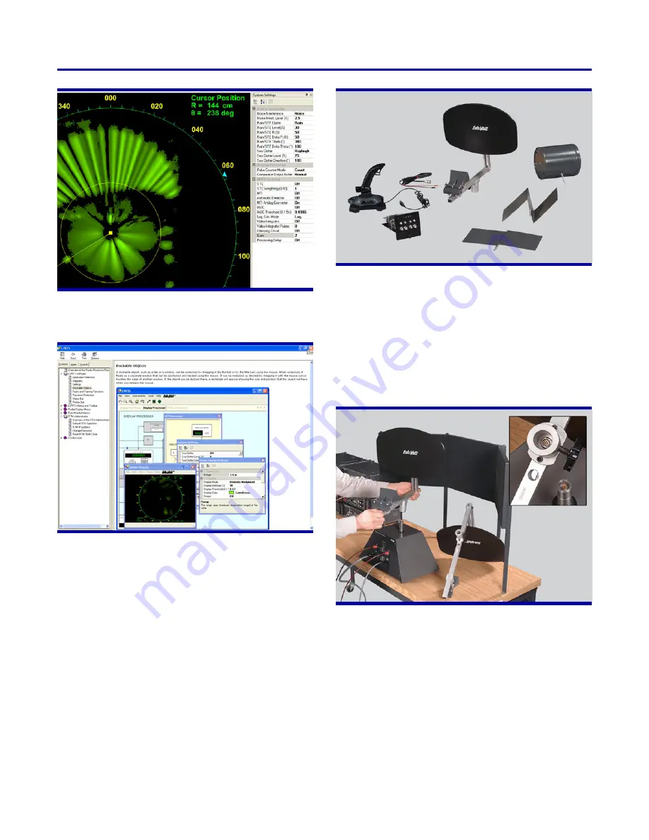
Figure 17. Antenna replacement is quick and easy thanks to
miniature plug-in connectors in the antenna frame and antenna
pedestal's shaft.
The Radar Tracking Training System, Model 8096-3,
adds on to the pulse radar implemented with the Basic
Radar Training System and the Radar Processor/Display
(Models 8096-1 and 8096-2, respectively), to form a
continuous tracking radar. This radar can track a passive
target that moves in the classroom laboratory. The
Radar Tracking Training System includes an interface
module to be installed in the RTM of the Radar Proces-
sor/Display, a special dual-feed parabolic antenna, a
joystick-type hand controller, a set of accessories, and
a student manual.
Installation of the Radar Tracking Training System is
very simple: insert the interface module in the RTM,
modify a few connections, connect the hand controller to
a USB port of the host computer, and replace the
conventional parabolic antenna with the dual-feed
parabolic antenna. These two antennas come with a
miniature plug-in connector to facilitate replacement, as
shown in Figure 17.
The tracking radar can operate in three different
modes (Scan, Manual, and Lock), which is selected
through the hand-controller buttons. In scan mode, the
antenna rotates at constant speed, allowing observation
of targets on the PPI display. In manual mode, the
operator can isolate a fixed or moving target of his or her
choice, using the hand controller to control the antenna
beam angle and to position an electronic marker (range
gate) over the target echo signal. A computer-based
O-scope display is used to monitor the position of the

