RADAR TRAINING SYSTEM
MODEL 8096
18
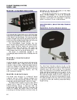
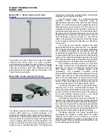
Model 9621 – Radar Receiver
The Radar Receiver is an instructional module designed
to provide training in system- and module-level
troubleshooting. It has switches that the instructor can
use to insert faults. These switches, as well as the circuit
boards and test points, are accessed through the hinged
door on top of the module.
The Radar Receiver down-converts the received
RF signal to baseband directly (homodyne receiver) for
the three types of radar that can be implemented (CW,
FM-CW, and pulse radars). Direct CW Doppler and
FM-CW outputs are provided. Quadrature detection
(I- and Q-channel outputs) is used for the pulse radar.
Wideband amplifiers are used in the I- and Q-channels
to ensure faithful baseband reproduction of the received
RF signals.
Unregulated DC power is automatically supplied to
the Radar Receiver through self-aligning connectors
when it is installed on the Power Supply / Antenna Motor
Driver.
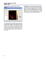
Model 9689 – Connection Leads and Accessories
The Model 9689-00 Connection Leads and Accessories
contains all of the cables and accessories necessary for
operation of the Basic Radar Training System,
Model 8096-1. These include; SMA flexible cables, BNC
cables, a DB9 cable, an antenna motor driver cable,
BNC tees, SMA attenuators, an SMA 50-
Ω
load, a
measuring tape, a level, a waveguide-to-coax adapter,
a horn antenna support, and quick-lock fasteners.
SUBSYSTEM 8096-2, RADAR PROCESSOR/DISPLAY
Model 9408 – Power Supply
The Power Supply is the power source for the
Reconfigurable Training Module (RTM), Model 9431. It
has two multi-pin connector outputs, located on the back
panel, that provide regulated DC voltages. Each output
can supply power to one RTM. Auto-reset fuses protect
the Power Supply outputs against short-circuits.
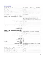
Model 9431 – Reconfigurable Training Module
The Reconfigurable Training Module (RTM) is the
cornerstone of the Radar Processor/Display. It consists
mainly of a powerful digital signal processor (DSP) and
three slots on the module's front panel for installing
interface modules. An Ethernet port (RJ-45) connector,
located on the back panel, allows connection of the RTM
to the radar host computer. The functionality of the radar
system (analog pulse radar, digital pulse radar or
tracking radar) is determined by downloading a program

