RADAR TRAINING SYSTEM
MODEL 8096
20
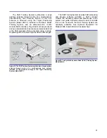
Model 9632 – Analog/Digital Output Interface
The Analog/Digital Output Interface is a compact module
designed to be installed into one of the slots on the RTM
of the Radar Processor/Display. This module provides
analog and digital output signals generated by the RTM.
The nature of the signals generated depends on the type
of radar processing that the RTM performs.
The Analog/Digital Output Interface has four
BNC-connector analog outputs and four BNC-connector
digital outputs. All these outputs are protected from
misconnections within the system. Test points are
available on the module's front panel to observe the
output signals using a conventional oscilloscope.
DC power is automatically supplied to the
Analog/Digital Output Interface when it is installed into the
RTM.
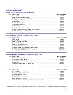
Model 9689-A – Connection Leads and
Accessories
The Model 9689-A Connection Leads and Accessories
contains a DB15 cable, a USB port cable, an RJ-45
connector crossover cable, an Ethernet adapter (network
card) to be installed in the radar host computer, two
semi-circular targets, a multiple target holder to be used
with the Target Positioning System, and the
LVRTS software CD-ROM.
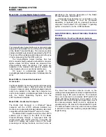
Model 9695 – Radar Host Computer
The Radar Host Computer is a Windows
®
based
computer with the LVRTS software installed, two
monitors, and a dual-output display adapter (video card)
compatible with Microsoft DirectX
®
version 9 or later.
The Radar Host Computer is used to run the LVRTS
software and is linked to the RTM of the Radar
Processor/Display through a high-speed data link
(Ethernet link with TCP/IP protocol). It provides the
radar's PPI display and allows control of the radar
processing and display functions, and much more as
described in the General Description of the Radar
Processor/Display, Model 8096-2.
The Radar Host Computer is not included in the
Radar Processor/Display. It must be purchased
separately or replaced with an equivalent personal
computer. The Windows
®
XP or Windows
®
7 operating
system is required to run the LVRTS software.
SUBSYSTEM 8096-3, RADAR TRACKING TRAINING
SYSTEM
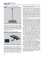
Model 9604-A – Dual Feed Parabolic Antenna
The Dual Feed Parabolic Antenna mounts on the
rotating antenna pedestal and is fully compatible with the
miniature plug-in RF quick connector. The dual-feed
horns are connected to a microwave SPDT switch that
allows alternating transmission and reception of the
signal from each horn through the single rotary joint of
the antenna pedestal. Switch control is achieved by
superimposing a DC bias on the transmitted RF signal.
The antenna beams formed by each horn are squinted
in azimuth to allow lobe switching (sequential lobing)
target tracking.


