20 Industrial Way, Rochester, NH 03867
•
603.335.6300 • Fax 603.335.3355
1355 Kuehner Drive, Simi Valley, CA 93063
•
800.900.9276
•
Fax 800.559.1583
(Sales, Service)
480 S. Service Rd. West, Oakville, Ontario, Canada L6K 2H4
•
905.844.8233
•
Fax 905.844.2635
www.Laars.com
Litho in U.S.A. © Laars Heating Systems 0603
ASSEMBLY
Mount the boiler to the wall with the paper template provided with the boiler itself, and following the
instructions given in the boiler manual. Use the heating delivery and return fittings (see fittings legend) on
the rear of the boiler and move the G 1” blind caps on the horizontal fittings (external boiler coil fittings).
Proceed as follows:
- Free space of at least 47.25 inches underneath the boiler
- Boiler spacing 31.5 inches (free space between boilers 7.8 inches).
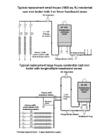
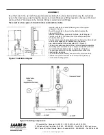
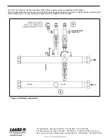
Install the kit pipes as given in the diagram in figure 2.
Mount the manifolds to the wall with suitable brackets (the pipes weigh 21 kg per boiler).
The main manifolds must be connected by tightening the G 2 1/2” nuts with a wrench of at least 600 mm length. Use a pipe with a G
1 1/2” fitting screwed onto one of the two free fittings on the male collector to stop it turning while doing so.
Install the safety valve, provided in the boiler, to its fitting (ref. 1 Figure 3) with the G 3/4” elbow.
Mount the safety valve outlet to a siphon drain pipe.
The expansion vessel (not supplied with the kit) must be dimensioned for the overall capacity of the installation in the normal way,
and connected to one of the fittings on the return manifolds (ref. 2 Figure 3).
We recommend dividing up the required total capacity by installing an expansion vessel to the G 3/4” fittings of each boiler (ref. 3
Figure 3) on the return connections (in this case, do not use the G 3/4” cap).
The heating system must be separated hydraulically from the delivery and return manifolds with a hydraulic separator (G 2 1/2”
fittings). The pump supplied with the kit pumps the water between the boiler and the manifolds.
The G 2 1/2” caps install on the terminating section of the left most boiler.
The G 1 1/2” caps install on the free fittings of each manifold.
Figure 2: Installation diagram


