20 Industrial Way, Rochester, NH 03867
•
603.335.6300 • Fax 603.335.3355
1355 Kuehner Drive, Simi Valley, CA 93063
•
800.900.9276
•
Fax 800.559.1583
(Sales, Service)
480 S. Service Rd. West, Oakville, Ontario, Canada L6K 2H4
•
905.844.8233
•
Fax 905.844.2635
www.Laars.com
Litho in U.S.A. © Laars Heating Systems 0603
ASSEMBLY
Mount the boiler to the wall with the paper template provided with the boiler itself, and following the instructions
given in the boiler manual. Use the heating delivery and return fittings (see fittings legend) on the rear of the boiler
and move the G 1” blind caps on the horizontal fittings (external boiler coil fittings).
There must be a free space of at least 55 inches underneath the boiler.
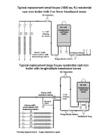
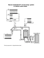
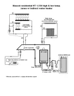
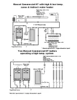
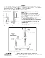
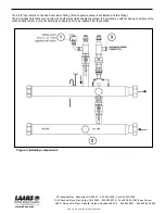
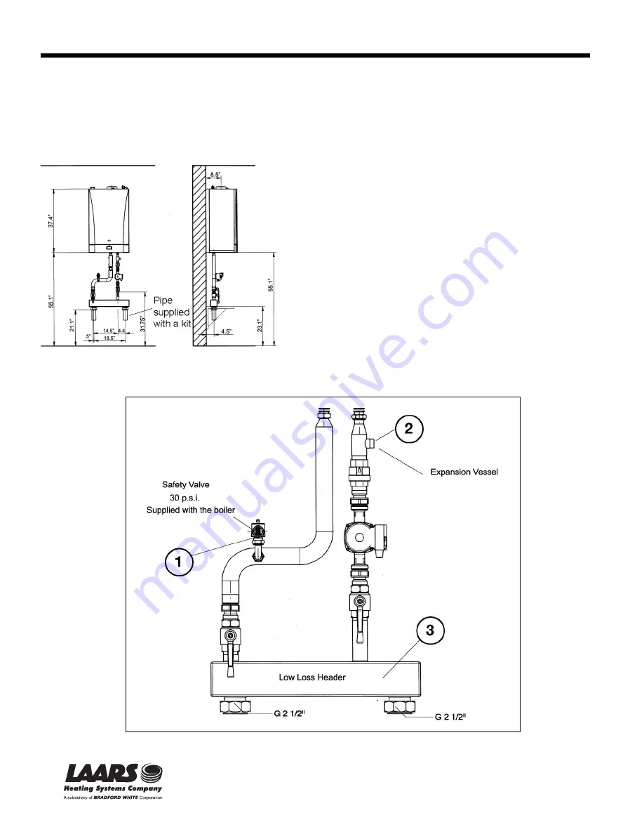
Install the kit pipes and accessories as given in the diagram
in figures 2, 3 and 5.
Mount the manifolds to the wall with suitable brackets (the
pipes weigh 20 kg).
Install the safety valve, provided in the boiler, to its fitting (ref. 1
Figure 3) with the G 3/4” elbow. Mount the safety valve outlet
to a siphon drain pipe.
The expansion vessel (not supplied with the kit) must be dimensioned
for the overall capacity of the installation in the normal
way, and connected to the check valve (ref. 2 Figure 3).
The low loss header supplied with the hydronic package separates
the heating plant circulation so as to keep a constant flow of water
in the boiler independently of losses of load (ref. 3 Figure 3).
The pump supplied with the kit pumps the water between the
boiler and the manifolds.
The kit includes boiler delivery and return shut-off valves which
enables the system to be worked on without having to empty
out the entire heating system.
Figure 3: Installing components
Figure 2: Installation diagram


