background image

Page 10

LAARS Heating Systems

1D. Cleaning the Combustion

Chamber Coil

Note

: In normal operation this procedure is

seldom required. Should it prove necessary, the
following procedure is used to access the coil for
cleaning.

1.

Turn off gas and electrical power to unit.

2.

Remove upper and lower front covers.

3.

Disconnect flue and combustion air pipes and
remove jacket top.

4.

Remove flue pipe assembly by disconnecting
from outer shroud.

5.

Remove mixer tube and blower assembly.

6.

Remove igniter and burner (flameholder).

7.

Fit mask and eye protection.

8.

Fit mask and eye protection.

9.

Locate vacuum hose at flue outlet of outer
shroud and start vacuum cleaner.

10.

Bend air chuck extension 90° at a point about
2-3" from end.

Insert air chuck extension through burner hole in

upper head. Direct end of extension toward fins of
heat exchanger and blow off accumulated residue.
Methodically move up and down and completely
around the heat exchanger. After completion of this,
remove the extension from the burner hole and inspect
the condition of the heat exchanger with a flashlight
and inspection mirror. If there are areas on the heat
exchanger that still have some residue, repeat the
process on those areas until the heat exchanger is
clean.

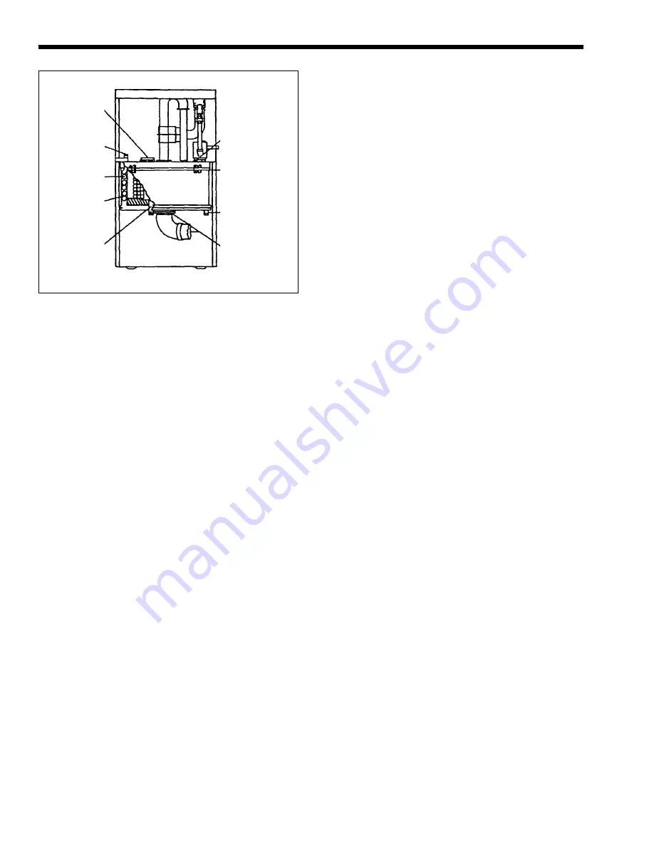
Figure 8. Disassembly.

After the heat exchanger is clean, remove the

vacuum cleaner from the outer shroud flue outlet and
stop vacuum cleaner.

Carefully inspect the seal between the outer

shroud and the upper head and the joint in the outer
shroud. If there is any evidence of leakage from either
of these joints, clean off the silicone in that area and
prepare the surface for resealing. Commercially
available oven cleane is an appropriate cleaning agent.
Reseal the affected areas witih silicone, reassemble all
parts in the reverse order and check boiler operation.

1E. Diverting Valve

The diverting valve is a thermostatically

controlled device which keeps the primary heat
exchanger (H-X) from operating in the condensing
mode. When return water from the storage tank or the
system is below 130°F (54°C) the diverting valve
recycles a portion of the outlet water from the primary
H-X back to the primary H-X inlet so that the
minimum temperature required to prevent
condensation on the primary H-X is maintained at
160°F (71°C). The thermostat element is similar to
those used in large industrial engines.

To change the thermostatic element, valve off

the unit and turn off electrical power. Open boiler
drain to relieve pressure and close again. Remove the
cap screws (3) and remove top of valve. Remove and
replace the element (with barrel up), spring and sealing
disc. Place O-ring under valve top and replace top.
Secure with cap screws and tighten. Turn on valves
and bleed air from the top of the diverting valve. Turn
on electrical power and restart unit.

1F. Safety Limit Switch

The Safety Limit Switch has a fixed set point of

245ºF (118°C). It has a manual reset button which
may be reset at temperatures below 240ºF (116°C).

To replace the switch, shut off the 120 volt

power and valve off the unit. Drain a gallon of water
from the boiler and remove the 3/8 NPTM fitting
which seals the capillary. Remove the two screws
which hold the switch to the side panel, remove the
switch and unplug the switch wires. Install the
replacement in the reverse order, open isolation valves
and bleed air from the diverting valve petcock. Switch
on 120 volt power and restart unit.

1G. Boiler Control

The boiler control controls the combustion

process, the gas valve, the igniter, the blower, and the
unit pump.

It provides blower prepurge as well as burner

flame sensing. When replacing the boiler control all
plugs are color coded and it is not possible to miswire
the control. See sequence of operation for operating
details.

ECONOMIZER
RETAINERS (4)

OUTER SHROUD
CLAMPS (4)

COLD WATER
INLET

PLASTIC FLANGE,
(4) NUTS

COMBUSTION

COIL

MANIFOLDS

ECONOMIZER

OUTLET

ECONOMIZER

INNER

SHROUD

MANIFOLD

DRAIN

Summary of Contents for HWG-M2-250

Page 1: ...r installation and or operation will void the warranty WARNING If the information in this manual is not followed exactly a fire or explosion may result causing property damage personal injury or loss...

Page 2: ...h 10 1G BoilerControl 10 1H Stack Switch 11 1I Igniter 11 1J Transformer 11 1K Unit Pump 11 1L Blower 11 1M GasValve 11 1N TimeDelayRelay TDR 11 1O OperatingControl 11 1P VentTCO 12 1Q IntakeTCO 12 1R...

Page 3: ...ondensation temperature of the water vapor in the flue gases A circulator is built into the unit to provide enough head to circulate water through the H X s and to a secondary heating loop or separate...

Page 4: ...pical D Combustion Coil Outlet E Hot Water Outlet To Tank or System 160 170 F Typical 160 FTHERMOSTAT Figure 2a Water Flow through a Heatmaker 9600 HWG Before S N 394 068 CB Before S N 795 0014 THERMO...

Page 5: ...urner 8 Secondary Heat Exchanger 9 Primary Heat Exchanger 10 Return From Primary Loop 11 Gas Valve 12 Flow To Primary Loop A Secondary Heat Exchanger Inlet B Secondary Heat Exchanger Outlet C Primary...

Page 6: ...ow Through Heatmaker 9600 43 INTAKE TERMINAL 50 WALL PLATE AIR INTAKE 45 WALL PLATE 44 EXHAUST TERMINAL EXHAUST AIR ORIFICE GAS ORIFICE GAS 1 COMBUSTION COIL 2 ECONOMIZER 7 FLAMEHOLDER 46 EXHAUST ASSE...

Page 7: ...9600 CB HWG Service Manual Page 7 Figure 4 Cut Away View of Heatmaker 9600 Figure 5 Control Box...

Page 8: ...nd input desired Part Description Part 23 Jacket Front Removeable 10 402 24 Jacket Top 10 406 25 Jacket Bottom 10 010 26 Control Boiler Integrated 2400 224 27 Transformer 40 VA 2400 006 28 Time Delay...

Page 9: ...minal and at least 6 152mm into the flue pipe The unit must operate for 5 minutes before taking a sample Take a sample and determine the CO2 or O2 CO2 8 to 8 5 natural gas O2 7 to 6 CO2 9 to 9 8 propa...

Page 10: ...ostatically controlled device which keeps the primary heat exchanger H X from operating in the condensing mode When return water from the storage tank or the system is below 130 F 54 C the diverting v...

Page 11: ...d unplug the power wires from the blower motor Disconnect intake exhaust vents and remove top jacket Remove the six bolts and nuts from the blower discharge flange and the four nuts from the blower in...

Page 12: ...n the gas valve The gas supply to the boiler must be shut off before making this connection The Heatmaker boiler is designed to operate with supply pressures of 4 14 in W C 8 1 oz in2 with the boiler...

Page 13: ...se the flame signal The control then causes a restart and if the flame signal is sensed on the restart then the burner will operate again The intermittent sending and losing of the flame signal by the...

Page 14: ...solution is no longer foamy 7 Shut off pump and disconnect from hose Carefully drain solution from hoses and connect city water to lower hose to flush combustion coil Flush for approximately 5 minutes...

Page 15: ...on and no indicator lights are flashing check for an open vent TCO operating control or safety limit switch For additionaltroubleshootinginformationrefertothe trouble shooting flow charts on the page...

Page 16: ...VOLTAGE 120 VAC BETWEEN BLACK AND WHITE WIRES AT BACK OF 120 VAC CONNECTORON BOILERCONTROL DIDBOILERRUNTHROUGHA COMPLETE CYCLE AS DE SCRIBED IN SEQUENCE OF EVENTS PAGE 20 TESTLIMIT CIRCUIT PAGE 17 PUM...

Page 17: ...OHMSCALE CONTINUITY CONTINUITY CONTINUITY NOCONTINUITY OHMS NOCONTINUITY TESTING LIMIT CIRCUIT YOU MUST COMPLETE PAGE 16 FIRST NOTE AFTER COMPLETEING LIMIT CIRCUIT TESTING PLUG IN CONTROL PLUG AND REC...

Page 18: ...EAVESETC AGAINST VENTTERMINAL CYCLE BOILER MANY TIMES TO TRY TO CREATE A MALFUNCTION CLEAR BLOCKAGE AND RECYCLEBOILER CHECKSTACKSWITCH BLOCKAGE EXISTS NO BLOCKAGE NO YES YES NO RED PURGE LIGHT FLASHIN...

Page 19: ...TSTACKSWITCH TUBES AND CHECK FOR CONTINUITYBETWEENSTACK SWITCHTERMINALSWITH BLOWEROPERATING CHECKFORVENTOBSTRUCTIONS CLEAROBSTRUCTIONS RECONNECTTUBES ELEC TRICALWIRESTOSTACK SWITCH START BOILER RUN TH...

Page 20: ...SSURETAP ON GAS VALVE PRESSURE DURING BLOWER OPERATIONWITHOUTGASFLOW VALVE FLAME LIGHT NOT LIT IS 4 IN W C CHECK FOR VOLTAGE 120 VAC ATBLOWERWIRECONNECTOR WITHIN5MINS AFTERGREEN LIGHT BLOWER O K REPLA...

Page 21: ...G LITE CHECKCOMBUSTION CHECKIGNITER IGNITEROK CHECK FOR GAS FLOW IS METER MOVING REPLACE IGNITER REPLACEINTEGRATEDBOILERCONTROLP N2400 224 INSTALL CORRECT ORIFICES BOILERCYCLESTHROUGHTHREECYCLESAFTER...

Page 22: ...L PLUG CN6 THERE IS 120 VAC AT CIRCULATOR PLUG CN5 TURNUPT STATORAQUASTATOR CORRECTSTATPROBLEM NO YES NO YES SEETROUBLESHOOTING CHART PAGE 16 THERE IS 120 VAC AT PUMP REPLACEBOILER CONTROLP N2400 224...

Page 23: ...23 Figure 9 9600 Ladder Diagram Figure 10 9600 Wiring Diagram Caution Label all wires prior to disconnection when servicing controls Wiring errors can cause improper and dangerous operation Verify pr...

Page 24: ...sure of 9 3 Remove blower and inspect flameholder burner for hole 4 Check that the blower flanges and gas piping are sealed D OCCASIONAL LOCKOUTS Requires interruption of power to re start or reset of...

Reviews: