


9600 HWG Water Heater
Page 7
Cold water supply piping, fittings and accessories.
1.
Install a strainer between the 9600 HWG and the
system. For proper pipe size and distance
limitations, refer to Table 3.
2.
Connect a drain valve and a shut off valve to the
9600 HWG cold inlet. On multiple units install a
check valve at each unit’s cold water inlet.
3.
Where check valves have been installed on cold
water inlet piping, check to be sure system has
an adequately sized expansion tank to allow
thermal expansion to occur.
Hot water supply piping.
Follow the manufacturer’s guidelines for
completion of the hot water system connections.
NOTE: A listed temperature and pressure
relief valve listed as complying with the Standard
for Relief Valves and Automatic Gas Shutoff
Devices for Hot Water Supply Systems, 1). ANSI
Z21.22 latest edition, or 2). CAN / CGA 1 - 4.4, of
suitable discharge capacity must be installed in the
separate storage tank system.
3.4 Tank Temperature Control
The 9600 HWG is turned on and off by a remote
tank aquastat. Locate the aquastat above the cold
water inlet fitting in the separate storage tank. The
9600 HWG draws water off the bottom of the tank
and pumps hot water back into the tank. When the hot
water level reaches the level of the aquastat, the
aquastat switch will open and turn off the 9600 HWG.
Please contact your factory representative if you
have any questions about storage tank application.
If a water heater is installed in a closed water
supply system, such as one having a backflow
preventer in a cold water supply line, means shall be
provided to control thermal expansion, such as a
properly sized potable water expansion tank.
If the relief valve on the appliance discharges
periodically, this may be due to thermal expansion in
Table 3. Water pipe and tube sizing between unit and tank.
Note:
This unit must be installed in a pressurized closed
system that maintains a minimum of 10 psi static pressure.
*
If water hardness is greater than 10 grains, a water soft-
ening or particle suspension device must
be installed be-
fore the heater, or warranty will be void.
Copper tube or
pipe size
Maximum
allowable tubing
length
Amount
deducted for
each additional
90° elbow
Amount
deducted for
each additional
45° elbow
1¼"
40'
2'
1½'
1½"
120'
2'
1½'
2"
270'
2'
1½'
a closed water supply system. Contact the water
supplier or local plumbing inspector on how to correct
this situation. Do not plug the relief valve.
No valves shall be placed between the tank T &
P relief valve and the tank. Pipe the outlet from the
relief valve such that any discharge from the relief
valve will be conducted to a suitable place for
disposal when relief occurs. Do not reduce line size or
install any valves in this line. The line must be
installed to allow complete drainage of both the valve
and the line.
3.5 Condensate Drain Connection
A black plastic fitting (labeled CONDENSATE)
is located on the side of the cabinet. This fitting will
accept 1/2" OD plastic tubing.
1.
Connect a plastic tube between the fitting and
the floor drain or condensate pump if a floor
drain is not accessible.
NOTE:
Connecting tubing must run
DOWNWARDS from the level of the fitting. See
Figure 8.
2.
Above the fitting is a hole in the cabinet. Behind
this hole is a 1/2" OD tube which serves as a
condensate relief if the lower drain becomes
blocked (see Figure 9).
3.
Run this condensate relief tube through the hole
in cabinet and to a drain pan. DO NOT pipe in
common with condensate drain fitted in A
above.
3.6 Electrical Connections
All electrical wiring must conform to local codes
and/or the 1). National Electrical Code ANSI/NFPA
No. 70-Latest Edition, or 2). The CSA Standard C22.1
“Canadian Electrical Code - Part 1”.
Single pole switches, including those of safety
controls and protective devices must not be wired in a
grounded line.
All electrical connections are made in the field
wiring box which is located on the left side of the
unit.
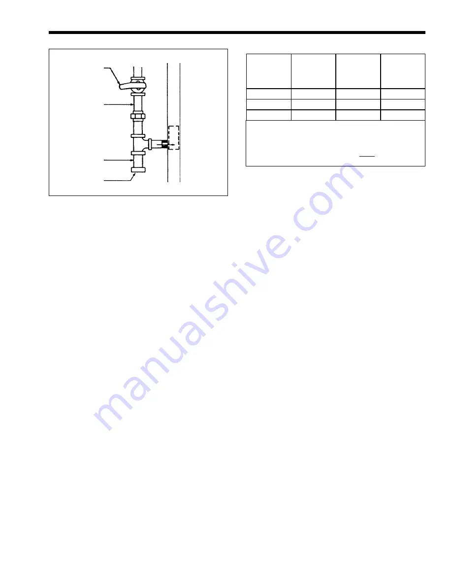
Figure 5. Gas supply piping.
To
9600 HWG
Manual Main
Shut Off
Gas Supply
Drip Leg
Cap


