29
Inverter Voltage Window Upper Limit
The maximum allowable/acceptable limit on the Inverter Voltage defaults to the Output Voltage s10%.
Thus, an inverter with an output voltage of 120 Volts will have a default setting of approximately 132 Volts.
There are no limits on max and min settings for this. The display units are in Volts-RMS. Due to display
resolution, the ability to adjust this setting to an exact voltage may not be possible. Inverters with higher output
voltages will have less accurate adjustments than those inverters with lower output voltages. The display will
alternate between “
-ILH
” and the upper limit setting.
Inverter Voltage Window Lower Limit
The minimum allowable/acceptable limit on the Inverter Voltage defaults to the Output Voltage setting -10%.
Thus, an inverter with an output voltage of 120 Volts will have a default setting of approximately 108 Volts.
There are no limits on max and min settings for this. The display units are in Volts-RMS. Due to display
resolution, the ability to adjust this setting to an exact voltage may not be possible. Inverters with higher output
voltages will have less accurate adjustments than those inverters with lower output voltages. The display will
alternate between “
-IL
L” and the lower limit setting.
Inverter Sense Delay
This setting is used to set the amount of time the Inverter Voltage must be within the upper and lower limits
described above for the logic to consider the Invert Voltage to be within tolerance. The Inverter Sense Delay
may be adjusted from 0 to 10 seconds in 1-second increments, with 10 being the default. The display will
alternate between “
-Id-
” and the time delay setting.
Utility Sense Delay
This setting is used to set the amount of time the Utility Voltage must be within the upper and lower limits
described above. The Utility Sense Delay may be adjusted from 0 to 10 seconds in 1-second increments, with
10 being the default.
The display will alternate between “
-Ud-
” and the time delay setting.
Re-Transfer Delay
This setting is used to set the time the inverter will attempt to retransfer from the Alternate Source back to the
Primary Source. The inverter must be in Auto Re-Transfer Mode for this setting to have any effect. The Re-
transfer Delay may be adjusted from 0 to 20 seconds in 1-second increments, with 20 being the default. The
display will alternate between “
-rd-
”
and the time delay setting.
Hit Counter
This setting is used to determine the maximum allowable Load Voltage deviations outside of the predefined
envelope that will trigger a transfer. The Hit Counter may be adjusted from 1 to 40 hits, with 3 being the
default setting. The display will alternate between “
-HC-
”
and the hit count setting.
Modbus Address
This setting changes the address of the Modbus. The default address is 1. The display will alternate between
“Addr” and the address setting.
Modbus Baud Rate
This setting changes the Modbus Baud Rate. The default baud rate is 9600. The display will alternate between
“bAud” and the baud rate setting.
The baud rate of the AUPS system should be set to match the baud rate of
the computer that is connected.
Summary of Contents for 7.5K-A1-BD3-125V100A
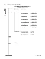
Page 30: ...24 3 6 3 Rectifier Customer Configuration Menu AUPS Rectifier Customer Configuration Menu ...
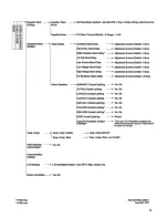
Page 31: ...25 ...
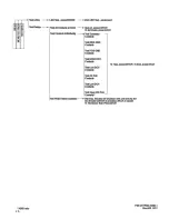
Page 32: ...26 ...

