background image


INFOSEC UPS SYSTEM - 15, rue du Moulin - 44880 Sautron - FRANCE - www.infosec-ups.com 

Hot Line 

– Tel + 33 (0)2 40 76 15 82 - Fax + 33 (0)240 94 29 51 - [email protected] – 04 17 AA 59 201 06 


USER MANUAL 


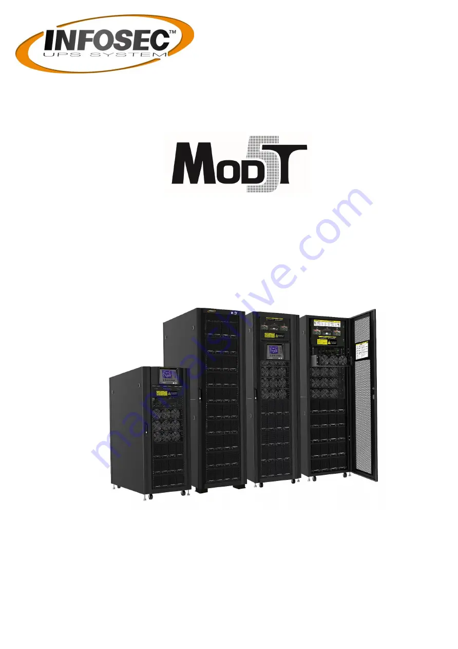
Three phases Modular UPS Solutions:   

30 kVA to 300 kVA HV 

For 30 kVA modules   


Summary of Contents for Mod5T 120/30

Page 1: ...du Moulin 44880 Sautron FRANCE www infosec ups com Hot Line Tel 33 0 2 40 76 15 82 Fax 33 0 240 94 29 51 hotline infosec fr 04 17 AA 59 201 06 USER MANUAL Three phases Modular UPS Solutions 30 kVA to 300 kVA HV For 30 kVA modules ...

Page 2: ...le Installation 33 3 Operation Mode and UPS Operation 34 3 1 Block diagram of UPS 34 3 2 Operation Mode 36 3 3 UPS Operation 43 4 Control Panel and Display Description 54 4 1 Introduction 54 4 2 Screen Description 55 4 3 Alarm List 79 4 4 History Record 81 5 Interface and Communication 83 5 1 Dry Contact Port 83 5 2 Extra Comm Slot 85 5 3 Local Communication Ports RS232 USB 85 5 4 SNMP Slot 85 6 T...

Page 3: ...ment installation restrictions or additional measures may be needed to prevent disturbances This logo means that the 220V 230V 240V HV product answers to the EMC and LVD standards regarding to the regulation associated with the electric equipment voltage and the electromagnetic fields This is a category C3 UPS product This category includes UPS with an output current exceeding 16 A and intended fo...

Page 4: ... grounded If it is remove the source of grounding Contacting with any part of the ground might result in electrical shock The likelihood of such shock can be prevented if such grounds are removed during installation and maintenance UPS is designed to supply power even when disconnected from the utility power After disconnect the utility and DC power authorized service personnel should attempt inte...

Page 5: ...the front of the cabinet and exhausted through grills located in the rear part of the cabinet Please do not block the ventilation holes 4 Ensure that the installation area is spacious for maintenance and ventilation 5 Keep the temperature of installation area around 30 C and humidity within 90 The highest operating altitude is 1000 meters above sea level 6 If necessary install a system of room ext...

Page 6: ...e unit Make sure that nothing inside the package is damaged Please keep the original package in a safe place for future use S versions means without batteries space Voltage 3 x 380V N 3 x 400V N 3 x 415V N 1 Use a forklift to move the product to installed area Refer to Figure 2 1 Please make sure the bearing capacity of forklift is sufficient 2 Please follow the orders in Figure 2 2 to remove cart...

Page 7: ... 2 2 3 Put a ramp in the front of the cabinet and insert small wood into groove Then remove two side panels Refer to Figure 2 3 Figure 2 3 4 Remove 4 fixing cabinet plates and loosen leveling feet by rotating them counterclockwise Then move the cabinet from the pallet Refer to Figure 2 4 5 To fix the cabinet in position simply rotate leveling feet clockwise Refer to Figure 2 5 ...

Page 8: ...ed from the pallet to ground we suggest that at least three people move the UPS to the installation area One person holds a lateral side of the UPS with hands another holds the other lateral side of the UPS with hands and the other person pushes the UPS either from the front side or from the back side to the installation area and avoid tipping the UPS 3 The casters are designed to move on level gr...

Page 9: ...e and they can work as a stand alone UPS or be connected to battery externally The extended cabinets don t have the battery module compartments The battery has to be connected externally Please consider the external battery space and wiring gauge for installation Mod5T 90 30 Mod5T 120 30 Mod5T 120 30 S Mod5T 180 30 S Mod5T 210 30 S Mod5T 300 30 S Photo Cabinet Height 30U 42U 30U 30U 42U 42U Switch...

Page 10: ...d door lock The side panels are lockable The casters at the bottom of the UPS cabinet can be used to move over short distances There are four leveling feet to fix and stabilize the UPS cabinet on the ground Refer to Figure 2 7 Inside the cabinet there are Breakers STS Module Power Module slots and Battery module slots Battery Module Slots is only for standard series All wiring terminal blocks are ...

Page 11: ...n FRANCE www infosec ups com Hot Line Tel 33 0 2 40 76 15 82 Fax 33 0 240 94 29 51 hotline infosec fr 04 17 AA 59 201 06 2 6 1 Mechanical Data Dimensions UPS cabinet Width Depth Height 30U 600mm 1100m 1475mm 42U 600mm 1100m 2010mm Figure 2 8 Dimensions ...

Page 12: ...w Unlock and open the front door and you will see the Main Breaker Q1 Maintenance Breaker Q2 Output Breaker Q3 STS Module Power Module slots and Battery Module slots Battery Module Slots is only for standard series The cabinet of 300K Model has Maintenance Bypass Switch Only Mod5T 120 30 42U Mod5T 210 30 S 42U Mod5T 300 30 S 42U 1 Switch Unit 2 STS Module 3 Power Module 4 Battery Module ...

Page 13: ... hotline infosec fr 04 17 AA 59 201 06 2 6 3 Rear View Unlock and open the rear door and you will see the rear panel of UPS There is a Battery Breaker for internal battery modules in the standard series but there is not any in the extended series S versions Mod5T 120 30 42U Mod5T 210 30 S 42U Mod5T 300 30 S 42U Figure 2 10 Rear View ...

Page 14: ...59 201 06 2 7 Internal Mechanisms 2 7 1 1 Breakers After opening the front door there are three breakers Main Breaker Q1 Maintenance Breaker Q2 and Output Breaker Q3 For the standard series there is a battery breaker for internal battery modules You can see it when you open the rear door Mod5T 120 30 42U front Mod5T 210 30 S 42U front Figure 2 11 Front Breakers ...

Page 15: ...EM 15 rue du Moulin 44880 Sautron FRANCE www infosec ups com Hot Line Tel 33 0 2 40 76 15 82 Fax 33 0 240 94 29 51 hotline infosec fr 04 17 AA 59 201 06 Mod5T 90 30 30U Rear Mod5T 120 30 42U Rear Figure 2 12 Rear Breaker ...

Page 16: ...fosec ups com Hot Line Tel 33 0 2 40 76 15 82 Fax 33 0 240 94 29 51 hotline infosec fr 04 17 AA 59 201 06 2 7 1 2 Maintenance Bypass Switch After opening the front door there is one Maintenance Bypass Switch in the 300K cabinet Figure 2 12 1 Maintenance Bypass Switch ...

Page 17: ...er to Figure 2 13 No Item Function Description Output Block Connects the critical loads Includes R S T and Neutral terminals Bypass Input Block Connects bypass AC source Includes R S T and Neutral terminals Main Input Block Connects main AC source Includes R S T and Neutral terminals For UPS Grounding For UPS grounding Includes one grounding terminal Battery Input Block Connects an external batter...

Page 18: ... Moulin 44880 Sautron FRANCE www infosec ups com Hot Line Tel 33 0 2 40 76 15 82 Fax 33 0 240 94 29 51 hotline infosec fr 04 17 AA 59 201 06 Figure 2 14 Mod5T 120 30 42U Terminal Blocks Figure 2 15 Mod5T 210 30 S 42U Terminal Blocks ...

Page 19: ... in the friendly interface For detailed information please refer to Charter 4 Figure 2 16 Control Panel 2 8 2 LED Indicators LED Color Status Definition INPUT Green On Input source is normal Flashing Input source is abnormal out of limit Off No input source BYPASS Yellow On Load on Bypass Flashing Input source is abnormal out of limit Off Bypass not operating INVERTER Green On Load on inverters Of...

Page 20: ...essing ESC key Return to previous screen when screen is not in Main screen Return to previous value in the same row so you can change it For example when changing 4 digit password press Esc to allow cursor back to previous digit Up Left Key for menu page navigation or digit modification Down Right Key for menu page navigation or digit modification Enter Confirmation of commands or cursor displacem...

Page 21: ...e and Battery Module make maintenance and replacement quick and easy The modular and hot swappable design of Power Module makes it a highly cost effective solution to meet your power requirement The number of Power Modules installed in the UPS can be based on the initial needs Once the power requirement increases you can easily install more Power Modules without interrupting the operation of the s...

Page 22: ...iled information please refer to Charter 5 No Item Description Extra Comm Slot This slot can insert an optional card Extra Comm card which can enhance the communication capability of UPS system It can provide another SNMP slot and some dry contact ports LCD Port This port connects to Control Panel with a factory installed cable RS232 port Local communication interface USB port Local communication ...

Page 23: ...tch Unlock it before removing the Power Module Lock it when the Power Module is well installed Then the Power Module can start to work DIP Switches There are three DIP switches for Power Module address setting In the same cabinet each Power Module ID MUST be exclusive The setting method is shown in Table 2 1 Battery Start Button When AC input is not existing use this button to start battery power ...

Page 24: ...is located at the back of UPS cabinet Refer to Figure 2 20 Figure 2 20 Parallel Board The SW1 and SW2 position have been well installed before leaving factory It s not necessary to change it for single UPS system application But for Parallel UPS system application please follow the instructions in Chapter 9 UPS Installation for Parallel Rack System to adjust SW2 Standard single unit SW1 SW2 Module...

Page 25: ...25 INFOSEC UPS SYSTEM 15 rue du Moulin 44880 Sautron FRANCE www infosec ups com Hot Line Tel 33 0 2 40 76 15 82 Fax 33 0 240 94 29 51 hotline infosec fr 04 17 AA 59 201 06 ...

Page 26: ... 29 51 hotline infosec fr 04 17 AA 59 201 06 2 9 3 Battery tray The Battery Module is shipped with its own package The inside batteries can be installed at factory or installed by the end user A Battery Module contains 10 pcs of 12V 9Ah batteries at maximum Figure 2 21 Battery trays Figure 2 22 Internal Wiring of Battery trays ...

Page 27: ... 90KVA 120KVA 150KVA Current A 55 110 165 220 275 Power cable mm2 10 35 70 95 150 Fixation torque force lb in 20 20 20 20 20 Model 180KVA 210KVA 240KVA 270KVA 300KVA Current A 330 385 440 495 550 Power cable mm2 240 300 300 120 2 150 2 Fixation torque force lb in 20 20 20 20 20 Notice Installer has to consider the max current and wiring gauge when considering future extension 2 10 2 DC input maxim...

Page 28: ...ype of battery has to be used if the battery is in parallel application For Mod5T 120 30 S 30U Mod5T 180 30 S 30U Mod5T 210 30 S 42U and Mod5T 300 30 S 42U Model 30KVA 60KVA 90KVA 120KVA 150KVA Current A 100 200 300 400 500 Power cable mm2 25 95 150 240 120 x 2 Fixation torque force lb in 20 20 20 20 20 Model 180KVA 210KVA 240KVA 270KVA 300KVA Current A 600 700 800 900 1000 Power cable mm2 150 x 2...

Page 29: ...cation connect Input1 to the AC power source and use 3 short wires to connect Input1 and Input2 For Dual input application connect input1 to the Main AC power source and connect input2 to the Bypass power source The sequence of three phase R S and T must be connected accordingly The wrong sequence will alarm a warning when the UPS is powered The N must be connected firmly A warning message will be...

Page 30: ...inet Connection External Battery Cabinet Battery Battery Figure 2 24 External Battery Cabinet Wiring After the battery is completely installed be sure to set up nominal battery voltage battery capacity and maximum charging current in LCD setting Otherwise if battery setting is different from actual installation the UPS will keep warning Please refer to section 4 2 6 3 and Table 4 9 for the details...

Page 31: ...dule Installation The weight of Power Module is over 30Kg so at least two persons are required for handling 2 12 1 Insert the Power Module 1 Adjust the DIP switch positions to set the different Module Address Refer to Table 2 1 2 Place the ready switch on the front panel of the module to the position i e in unready state 3 Insert the Power Module into an unoccupied slot by two persons ...

Page 32: ...move the Power Module Before removing any Power Module make sure the remaining Power Modules can support the critical loads At least one Power Module MUST stay in the UPS cabinet except the UPS system is operating in Maintenance Bypass Mode 1 Turn the ready switch to the position 2 The Power Module FAULT LED RED indicator is lit to indicate the Power Module output is off and disconnected from UPS ...

Page 33: ...ion replacement make sure the Battery Breaker is in the OFF position 2 13 1 Insert the Battery Module Only Standard Series Cabinet 1 Open the UPS s front door and remove the panel of battery module slot 2 There are 4 rails for inserting the Battery Modules in the same layer Four Battery Modules MUST be installed to form a set of Battery 3 Regarding the maximum load of power modules please refer to...

Page 34: ...ww infosec ups com Hot Line Tel 33 0 2 40 76 15 82 Fax 33 0 240 94 29 51 hotline infosec fr 04 17 AA 59 201 06 3 Operation Mode and UPS Operation 3 1 Block diagram of UPS Wiring diagram for dual inputs 90KVA 210KVA Wiring diagram for dual inputs 300KVA Figure 3 1 ...

Page 35: ...Moulin 44880 Sautron FRANCE www infosec ups com Hot Line Tel 33 0 2 40 76 15 82 Fax 33 0 240 94 29 51 hotline infosec fr 04 17 AA 59 201 06 Wiring diagram for single input 90KVA 210KVA Wiring diagram for single input 300KVA Figure 3 2 ...

Page 36: ...nversion and reverse transfer UPS that permits operation in the following modes Standby Mode Line Mode Battery Mode Bypass Mode ECO Mode Shutdown Mode Maintenance Bypass Mode manual bypass 3 2 1 Standby Mode Upon connecting to utility input power the UPS is in Standby mode before UPS is turned on if BYPASS enable setting is Disabled and charger function will be active when the battery is present T...

Page 37: ... 51 hotline infosec fr 04 17 AA 59 201 06 3 2 2 Line Mode In Line Mode the rectifier derives power from the utility power and supplies DC power to the inverter and the charger charges the battery The inverter filters the DC power and converts it into pure and stable AC power to the load Figure 3 4 Line Mode Diagram Mod5T 300 30 S ...

Page 38: ... Mode The UPS automatically transfers to Battery mode if the utility power fails There is no interruption in power to the critical load upon failure In battery mode the rectifier derives power from the battery and supplies DC power to the inverter The inverter filters the DC power and converts it into pure and stable AC power to the load Figure 3 5 Battery Mode Diagram Mod5T 300 30 S ...

Page 39: ...S enable setting is Enabled and charger function will be active when battery is present After UPS has been turned on if the UPS encounters abnormal situations over temperature overload etc the static transfer switch will perform as a transference of the load from the inverter to the bypass source with no interruption If the transference is caused by a recoverable reason the UPS will turn back to l...

Page 40: ...nabled through the setting menu of LCD panel In ECO mode the load is powered by bypass when the bypass voltage and frequency are within the acceptable ranges If the bypass is out of range the UPS will transfer the power source of load from bypass to inverter In order to shorten the transfer time the rectifier and inverter are working when the UPS is in ECO mode Figure 3 7 ECO Mode Diagram Mod5T 30...

Page 41: ... the UPS is in the off state and the utility power source is absent the UPS will enter into shutdown mode Or when the UPS has discharged the battery to the cut off level the UPS will enter into shutdown mode as well When the UPS enters this mode it is going to shut off the control power of UPS The rectifier charger and inverter are all in off state Figure 3 8 Shutdown Mode Diagram Mod5T 300 30 S ...

Page 42: ...r 04 17 AA 59 201 06 3 2 7 Maintenance bypass Mode A manual bypass switch is available to ensure continuity of supply to the critical load when the UPS becomes unavailable e g during a maintenance procedure Before entering the maintenance bypass mode make sure the bypass power source is normal Figure 3 9 Maintenance Bypass Mode Diagram Mod5T 300 30 S ...

Page 43: ...2 9 2 Power Module Make sure the ready switch on the Power Module has been moved to the Locked position Make sure all the breakers are switch OFF 3 3 1 AC Startup Ensure to follow this procedure when turning on the UPS from a fully powered down condition The operating procedures are as follows Step 1 Refer to Chapter 2 Installation to connect the power cables and install the Power Modules and the ...

Page 44: ...osec fr 04 17 AA 59 201 06 Step 4 Switch ON the input breaker Q1 The UPS will enter into Standby Mode if the setting of Bypass mode is disabled Or the UPS will enter into Bypass Mode if the setting of Bypass mode is enabled Step 5 Make sure there is no warning or fault event happening If yes please refer to Chapter 6 Troubleshooting to solve it ...

Page 45: ... 51 hotline infosec fr 04 17 AA 59 201 06 Step 6 Press Power ON OFF button for two seconds to enter into Line Mode as shown below After turning on UPS will do self test and start Inverter up UPS will be transferred to Line mode when all power modules are ready Step 7 Switch ON the output breaker Q3 AC startup procedure is complete ...

Page 46: ...eaker Step 2 Press the Battery Start button on any one of Power Modules to start up the control power of all Power modules and STS moodule as shown below Battery Start Button Step 3 After pressing the Battery Start button UPS will enter into Standby mode Refer to the diagram below for LCD display Step 4 Before UPS enters into shutdown mode please press Power On Off button for 2 second immediately ...

Page 47: ...shown in the diagram below Step 6 Switch ON the output breaker Q3 Cold start startup procedure is complete 3 3 3 Maintenance Bypass Operation Follow the instruction to transfer to Maintenance Bypass and UPS protection as below 3 3 3 1 Transfer to maintenance bypass 90KVA 210KVA 300KVA Step 1 Remove the mechanical lock plate of Maintenance Bypass Breaker Remove the mechanical lock plate of Maintena...

Page 48: ... 201 06 Step 2 Make sure the UPS operates in Bypass mode as shown below Make sure the UPS operates in Bypass mode as shown below Step 3 Switch ON the Maintenance Bypass Breaker as shown below Switch the handle toward upside as shown below Step 4 Switch OFF the Main Breaker Q1 and Output breaker Q3 as shown below It is possible to change the STS module Power Module ...

Page 49: ...VA 300KVA Step 1 Make sure the maintenance is complete The Power Modules and STS module have been installed well Make sure the maintenance is complete The Power Modules and STS module have been installed well Step 2 Switch ON the Main Breaker Q1 and Output breaker Q3 as shown below Please enter LCD SETUP MENU and choose SYSTEM to ensure that the Bypass mode is enabled If the Bypass mode is disable...

Page 50: ... exit the SETUP menu and check if the UPS operates in bypass mode Switch the handle toward downside as shown below Step 4 Turn off Maintenance Bypass Breaker as shown below Lock back the mechanical lock plate as shown below Step 5 Lock back the mechanical lock plate as shown below 3 3 4 Turn off Operation 3 3 4 1 Bypass Mode Standby Mode Turn Off Operation When the UPS neither is turned on nor tur...

Page 51: ...1 06 Bypass Mode Setting is Disabled Bypass Mode Setting is Enabled Step 1 Switch OFF the Main Breaker The LCD diagrams are shown below Bypass Mode Setting is Disabled UPS enters Shutdown Mode It is normal the Un Connection is shown when Power Modules have shut off their control power Bypass Mode Setting is Enabled UPS stay in Bypass mode and No AC input is indicated ...

Page 52: ...AC power for a long time 3 3 4 2 Line Mode Turn Off Operation The LCD diagrams are shown below when the UPS operates in the Line Mode Step 1 Press Power On Off button for 2 second to turn off the UPS Or use the Menu Control System Turn Off to turn off the UPS After turning off the UPS will tranfer to Standby Mode or Bypass Mode It depends on the Bypass Mode Setting Next follow the Bypass Mode Stan...

Page 53: ...2 Fax 33 0 240 94 29 51 hotline infosec fr 04 17 AA 59 201 06 Step 1 Press Power On Off button for 2 second to turn off the UPS Or use the Menu Control System Turn Off to turn off the UPS After turning off the UPS will tranfer to Standby Mode Next follow the Bypass Mode Standby Mode Turn Off Operation procedure ...

Page 54: ...dications 3 Control keys 4 Audio Alarm as shown in Figure 4 1 Figure 4 1 Control panel 1 LCD display Graphic display and all measured parameters 2 LED indications Refer to Table 4 1 3 Control keys Refer to Table 4 2 4 Audible Alarm Refer to table 4 3 Table 4 1 LED indications LED Color Status Definition INPUT Green On Input source is normal Flashing Input source is abnormal Off No input source BYP...

Page 55: ...r displacement Home Return to Main screen Power On Off Turn on UPS or Turn off UPS Table 4 3 Audible Alarm Audio Type Description Power on off Buzzer sounds two seconds Battery mode Buzzer sounds every 2 seconds Low battery Buzzer sounds every half seconds UPS alarm Buzzer sounds every 1 second UPS fault Buzzer continuously sounds 4 2 Screen Description 4 2 1 Start Screen Upon starting the UPS exe...

Page 56: ...Time Figure 4 3 Main screen 4 2 3 MENU Screen In the Main Screen press ESC button to enter the MENU screen Use UP and DOWN buttons to choose different menus and Press ENTER to enter the sub screen as shown in Figure 4 4 and 4 5 Figure 4 4 Menu tree Figure 4 5 Menu screen 4 2 4 Control Screen Use UP and DOWN buttons to choose CONTROL option and press ENTER button to enter the submenu as shown in Fi...

Page 57: ...u Moulin 44880 Sautron FRANCE www infosec ups com Hot Line Tel 33 0 2 40 76 15 82 Fax 33 0 240 94 29 51 hotline infosec fr 04 17 AA 59 201 06 Figure 4 6 Control menu Figure 4 7 Control screen page 1 Figure 4 8 Control screen page 2 ...

Page 58: ...nd RIGHT buttons to choose YES or NO Choose YES and press ENTER button to confirm command or choose NO to cancel command as shown in Figure 4 9 Figure 4 9 Confirmation screen 4 2 5 Measurement Screen Use UP and DOWN buttons to choose MEASUREMENT option and press ENTER button to go into the submenu as shown in Figure 4 10 4 11 Figure 4 10 Measurement menu Figure 4 11 Measurement Menu Screen Use UP ...

Page 59: ... Factor Output Power Factor L1 L2 L3 Bypass L N Voltage V Bypass phase voltage L1 L2 L3 Units 0 1V Frequency Hz Bypass Frequency L1 L2 L3 Units 0 1Hz Power Factor Bypass Power Factor L1 L2 L3 Load Sout KVA Apparent power Units 0 1KVA Pout KW Active power Units 0 1KW Load Level The percentage of the UPS rating load Units 1 Battery Positive Voltage V Battery Positive Voltage Units 0 1V Negative Volt...

Page 60: ... Units 0 1 4 2 6 Setup Screen Use UP and DOWN buttons to choose SETUP options It s required to enter password to access General SYSTEM BATTERY PRE ALARM and PARALLEL sub menus as shown in Figure 4 13 Figure 4 13 Setup menu When the SETUP option is selected by pressing ENTER button it will pop up a screen requesting to enter password as shown in Figure 4 14 Figure 4 14 Enter password Screen It s re...

Page 61: ...ent operation mode The Table 4 5 lists the relevant information Table 4 5 All setting items in Setup Menu UPS operation Mode Setting item Standby Mode Bypass Mode Line Mode Battery Mode Battery Test Mode Fault Mode Converter Mode ECO Mode Authorization User Maintainer General Model Name Y Y Y Y Y Y Y Y Y Language Y Y Y Y Y Y Y Y Y Y TIME Y Y Y Y Y Y Y Y Y Change Password Y Y Y Y Y Y Y Y Y Y Baud R...

Page 62: ...Y Y Y Battery Test Interval Y Y Y Y Y Y Y Y Y Stop by Time Y Y Y Y Y Y Y Y Stop by Battery Voltage Y Y Y Y Y Y Y Y Stop by Battery Capacity Y Y Y Y Y Y Y Y Battery Age Alert Y Y Y Y Y Y Y Y Y Temperature Compensation Y Y Y Y Y Y Y Y Y Charging Voltage Y Y Y Pre Alarm Y Y Y Y Y Y Y Y Y Parallel UPS Parallel Y Y Y Independent Battery Y Y Y Y means that this setting item can be set in this operation ...

Page 63: ... Figure 4 17 Setup General Screen page 1 Figure 4 18 Setup General Screen page 2 Use LEFT and RIGHT buttons to choose the setting options for setting requirement then press ENTER The confirmation screen will pop up use LEFT and RIGHT buttons to choose YES or NO Choose YES and press ENTER button to confirm setting or choose NO to cancel the setting as shown in Figure 4 19 ...

Page 64: ...h TIME Adjust Time Set current date and time yyyy mm dd hour min sec MUST be set after UPS installation System Installed Date Set system installed date yyyy mm dd 2015 1 1 Default MUST be set after UPS installation System Last Maintain Date Set system latest maintenance date yyyy mm dd MUST be set after UPS installation Battery Installed Date Set battery installed date yyyy mm dd MUST be set after...

Page 65: ...the setting s you have done Table 4 7 EEPROM Reset Category list Setting Item Factory Reset EEPROM Reset General Model Name Language Y Y Adjust Time System Installed Date Y System Last Maintain Date Y Battery Installed Date Y Battery Last Maintain Date Y Change Password Y Baud Rate Y Audible Alarm Y Y Factory Reset EEPROM Reset EPO Function Y Save Setting System Output Voltage Y Bypass Voltage Ran...

Page 66: ...Test Interval Y Y Stop by Time Y Y Stop by Battery Voltage Y Y Stop by Battery Capacity Y Y Battery Age Alert Y Y Temperature Compensation Y Y Charging Voltage Y Y Auto restart battery voltage Y Y Pre Alarm Y 4 2 6 2 Setup System Screen Use UP and DOWN buttons to choose between different sub menus and press ENTER button to go into the SYSTEM setting screen as shown in Figure 4 20 4 21 4 22 Figure ...

Page 67: ...se check available setting item in Table 4 5 for the details If it s not set up in specific mode the warning screen will appear as shown in Figure 4 23 Figure 4 23 Warning screen Setup System setting list is shown in Table 4 8 Table 4 8 Setup System setting list Setting Item Sub Item Explanation Output Voltage Set output voltage 220Vac Default 230Vac 240Vac MUST be reviewed after UPS installation ...

Page 68: ... to low battery and then utility restores the UPS will return to line mode Cold Start Set cold start Disable Enable Default After Enable is set the UPS can be turned on without connecting to utility by pressing Battery Start Button Refer to cold start operation for the details Battery Mode Delay Time Set system shutdown delay time in battery mode 0 9990sec 0 Disable Default Not 0 Enable When this ...

Page 69: ...ing Setting Set Power Module Rating 20KVA 30KVA Default The 30K cabinet can be inserted with all 20KVA power modules For this kind of application the Power Rating has to be set to 20KVA If setting is not corresponding to power capacity of power module it will show error message MUST be reviewed after UPS installation Charger Test Set charger test Disable Default Enable 4 2 6 3 Setup Battery Screen...

Page 70: ...tery capacity 0 999 9Ah Default MUST be set after UPS installation or Battery capacity is changed Maximum Charging Current Set battery maximum charging current 1 128A 2A Default MUST be set after UPS installation or Battery capacity is changed Battery Low Shutdown SETTING Battery Low Voltage Set battery low voltage 10 5 11 5V x battery Number 11V x Battery Number Default Battery Low Capacity Set b...

Page 71: ... been installed over this period there is a warning Battery Age Alert to indicate it Temperature Compensation Set battery temperature compensation 0 5 mV cl 0 mV cl Default Charging Voltage Set battery charging voltage 2 30 2 35V 2 35V Default Set battery float voltage 2 23 2 35V 2 29V Default 4 2 6 4 Pre Alarm Screen Use UP and DOWN buttons to switch different sub menus Press ENTER button to go i...

Page 72: ...to switch between different sub menus Press ENTER button to go into the PARALLEL setting screen as shown in Figure 4 27 Figure 4 27 Setup Parallel screen See Setup Parallel setting list in Table 4 11 The warning Warning Parallel Firmware Error will appear in current event when the parallel setting is enabled but the firmware does not support this feature The way to release this warning is to turn ...

Page 73: ...check the serial number firmware versions system configuration and settings of the UPS There are submenus under the INFORMATION including Identification System and Battery as shown in Figure 4 28 4 29 Figure 4 28 Information menu Figure 4 29 INFORMATION screen 4 2 7 1 INFORMATION Identification Screen When Identification submenu is selected the Model Name Serial No and Firmware Version will be dis...

Page 74: ...ec fr 04 17 AA 59 201 06 Figure 4 30 Identification screen page 1 Figure 4 31 Identification screen page 2 4 2 7 2 INFORMATION System Screen When System submenu is selected the system power nominal voltage nominal frequency etc information will be displayed as shown in Figure 4 32 4 33 4 34 Use UP and DOWN buttons to switch between different pages ...

Page 75: ... FRANCE www infosec ups com Hot Line Tel 33 0 2 40 76 15 82 Fax 33 0 240 94 29 51 hotline infosec fr 04 17 AA 59 201 06 Figure 4 32 INFORMATION System screen page 1 Figure 4 33 INFORMATION System screen page 2 Figure 4 34 INFORMATION System screen page 3 ...

Page 76: ...u is selected the Battery nominal voltage capacity charging current etc information will be displayed as shown in Figure 4 35 4 36 Use UP and DOWN buttons to switch different pages Figure 4 35 INFORMATION Battery screen page 1 Figure 4 36 INFORMATION Battery screen page 2 4 2 8 Events Screen In EVENT menu you can check the current events history events and reset all events as shown in Figure 4 37 ...

Page 77: ...u will see flashing warning text in the Main Screen as shown in Figure 4 39 Figure 4 39 Alarm warning screen 4 2 8 1 Current Events When event occurs it will display Module ID and alarm code in Current Events screen It can save up to 50 events in current list Only 4 events can be listed in one page Therefore if it exceeds more than four you have to press UP or DOWN button to read other events as s...

Page 78: ...Refer to Table 4 12 Alarm List In order to record more historical information about the UPS system the important setting changed refer to Table 4 13 Important setting changed UPS operation mode changes refer to Table 4 14 UPS mode change and control action executes refer to Table 4 15 Control execution will be saved in History Events Refer to Figure 4 41 for display screen Figure 4 41 History Even...

Page 79: ...plete list of UPS alarm messages Table 4 12 Alarm List Representation in display LCD Explanation Fault Bus Over Voltage DC bus voltage is too high Fault Bus Under Voltage DC bus voltage is too low Fault Bus Voltage Unbalance DC bus voltage is not balanced Fault Bus Short DC bus is short Fault Bus Soft Start Time Out The rectifiers can t start due to low DC bus voltage within specified duration Fau...

Page 80: ...put Negative Power over range Fault Over Load Fault Heavy overload causes UPS fault Fault Battery Fault Batteries reversed Fault Over Temperature Make sure adequate space is allowed for air ventilation and the fan is working Fault CAN Fault CAN communication fault Fault TRIG0 Fault Synchronized trigger signal fault Fault Relay Fault Inverter relay fault Fault Line SCR Fail Line SCR short circuit f...

Page 81: ...er module ID conflict Pre Alarm Line Voltage Fail Line voltage over range Pre Alarm Line Voltage Normal Line voltage recovered to normal Pre Alarm Line Frequency Unstable Line frequency over range Pre Alarm Line Frequency Normal Line frequency recovered to normal Pre Alarm Over Load Output Load over range Pre Alarm Load Normal Output Load recovered to normal Pre Alarm Load Unbalance Output Load un...

Page 82: ... Setup Charging Voltage 42 Setup PRE ALARM 43 Setup UPS Parallel 44 Setup Independent Battery 45 Setup Auto restart battery voltage Table 4 14 UPS mode change Item No Description Item No Description 1 UPS Mode Power On Mode 2 UPS Mode Standby Mode 3 UPS Mode Bypass Mode 4 UPS Mode Line Mode 5 UPS Mode Battery Mode 6 UPS Mode Battery Test Mode 7 UPS Mode Fault Mode 8 UPS Mode Converter Mode 9 UPS M...

Page 83: ...nel Figure 5 1 Dry contact ports and communication ports Dry Contact No Function X1 Remote EPO input port X2 No use X3 No use X4 Maintenance Bypass Switch State Port X5 No use X6 Battery Cabinet Temperature Detection Port X7 No use X8 No use 5 1 Dry Contact Port 5 1 1 X1 Remote EPO Input Port The Emergency Power off EPO Function in UPS can be operated by an assigned remote contact Users can set th...

Page 84: ... is Normal Opened N O 5 1 2 X4 Maintenance Bypass Switch State Port X4 is the maintenance bypass switch port The port is shown in Figure 5 3 and described in Table 5 2 Figure 5 3 Maintenance Bypass Switch State port Table 5 2 Description of Maintenance Bypass Switch State port Name Position Description Maintain Bypass Pin1 X4 1 Maintenance bypass switch state Maintain Bypass Pin 2 X4 2 Maintenance...

Page 85: ...I C communication SDA Signal 3 0V X6 3 3V Power GND X6 4 GND 5 2 Extra Comm Slot There is an optional card Extra Comm Card which can be inserted into this slot This option can enhance the communication capability of the modular UPS It provides an additional SNMP Slot Dry contact I P O P signals and temperature sensors ports 5 3 Local Communication Ports RS232 USB Note The RS232 and USB ports can t...

Page 86: ...onnel Fault S Inverter Voltage Short S phase inverter Output is shorted Contact service personnel Fault T Inverter Voltage Short T phase inverter Output is shorted Contact service personnel Fault RS Inverter Voltage Short R S inverter Output is shorted Contact service personnel Fault ST Inverter Voltage Short S T inverter Output is shorted Contact service personnel Fault TR Inverter Voltage Short ...

Page 87: ...service personnel if necessary Warning Battery voltage High Battery voltage is too High Check the setting of Nominal Battery voltage and contact service personnel Warning Module Un Lock As stated Check if module is locked well Warning Turn On Abnormal As stated Check if the input voltage or frequency is out of range Warning Charge Fail As stated Contact service personnel Warning EEPROM Fail EEPROM...

Page 88: ... Cable Loosen As stated Check if the Parallel Rack Cable is loose and contact service personnel Warning Parallel Rack Config Wrong Parallel Rack Configure error Check the Parallel Rack Setting is correct and contact service personnel Warning Parallel Firmware Error Power module parallel firmware error The firmware version does not support Rack Parallel feature Contact service personnel Warning ID ...

Page 89: ...a screwdriver to remove the four screws from fixing holes 4 Two people pull out together and remove the Power Module from its slot 5 After servicing the module confirm that the DIP switch of the module is set correctly and the ready switch is in unready state 6 Push the module into the cabinet and tighten the screws on both sides If it s more than one power module to re install please wait 30 seco...

Page 90: ...Air Filter As shown below the UPS provides four air filters on the back of the front door Each filter is fixed by a fixing bar on both sides The replacement procedures of air filter are as follows 1 Open the front door of the UPS and the air filters are on the back of the door 2 Remove a fixing bar on either side of the air filter 3 Remove the air filter and insert a clean one 4 Replace the fixing...

Page 91: ...Distortion THDv 2 THD Linear Load 4 THD Non linear Load Efficaciency Up to 94 5 BATTERY CHARGER Nominal Voltage 240V 12V x 40 Pcs Floating Charge Voltage 2 25V element Boost Charging Voltage 2 35V element Temperature Compensation Yes Maximum Charging Current 8A for each power module ajustable MANAGEMENT COMMUNICATION Communication USB RS232 port supports Windows 2000 2003 XP Vista 2008 7 8 10 Linu...

Page 92: ...ervice personnel For the parallel system all firmware version of power modules must be 10 69 or higher and firmware version of LCD must be 09 50 or higher But once the system involved the new old version of power module or old LCD firmware it can t do the parallel system 9 1 Input and Output Wiring 1 When install the parallel rack system the input wires R S T N length of the Rack must be equal to ...

Page 93: ...e of Rack1 1 The parallel board s of the Rack 1 the SW2 must be set to the right side please refer to the figure 9 2 as below Warning For the cabinets which can insert more than 5 power modules there are two parallel boards inside the cabinet Both of these two SW2 have to be adjusted simultaneously 2 Refer to Table 2 1 to set the module address Figure 9 2 Rack 1 SW2 set to the right side 9 2 2 Ins...

Page 94: ...But keep the Output breakers Q3 of two Racks in the OFF position 3 Turn on the battery breaker 4 Turn on the external AC source breaker to apply AC Input source to two Racks 5 Wait for the wake up of UPSs Then start to set Rack 1 6 Through the panel of the UPS 1 Rack 1 set up the parallel function Enter the PARALLEL item in SETUP page Refer to User Manual 4 2 6 5 SETUP operation method 7 Enable th...

Page 95: ... each UPS must to be connected correctly the wrong connection will cause the UPS system cannot operate normally 9 5Parallel System Turn On Procedure 1 Please make sure the section 9 1 9 4 has been well followed 2 Please confirm the Input breaker and output breakers of each UPS Rack have already been turned ON 3 Turn On the battery Breaker 4 Turn on the external AC source breaker to apply AC Input ...

Reviews: