9
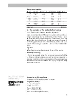
Energy consumption
Burners
Gas type
Pressure (kPa)
Injector (mm)
Mj/hr Watts
Small
Natural
1.0
0.90
3.85
-
LPG
2.75
0.54
3.25
-
Medium
Natural
1.0
1.18
7.12
-
(x2)
LPG
2.75
0.70
5.75
-
Large
Natural
1.0
1.55
12.5
-
LPG
2.75
0.92
11.25
-
Wok
Natural
1.0
1.65
13.1
-
LPG
2.75
0.95
13.1
-
Oven/Grill
3000 W
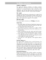
Test the operation of the cooker before leaving
Note: These burners have no aeration adjustment.
Check correct operation of the ignition system and operation of
burners individually and in combination. Burner flames should
be clear blue, with no yellow tipping. If the burners show any
abnormality check that burner heads are correctly located. If
satisfactory performance cannot be obtained, contact Sampford
& Staff or the local gas utility. For service contact number refer
below.
Important
Before leaving instruct the owner in the use of the cooker.
Warranty warning
It should be expressly noted that we cannot accept any liability
for direct or indirect damage caused by wrong connection or
improper installation. When being repaired, the appliance must
always be disconnected from the mains supply; if required, notify
our customer service.
For service to this appliance
For service to this appliance please contact:
Sampford & Staff P/L
52 - 70 Sparks Avenue
Fairfield, Vic, 3078
Phone:
1300 727 421
Fax:
1300 727 425
Email: [email protected]
This appliance is imported
and distributed by:
28
Service and
maintenance must be
carried out by an
authorised person
Always disconnect the gas supply and power before servicing
the cooker.
After service always check connections for gas soundness at
connections with soapy water. NEVER use a naked flame to check
for leaks.
To remove glass lid (for cookers fitted with a glass lid)
1. Place lid in the open position.
2. Lift the lid out of the hinge brackets.
3. Store in a safe place.
Access to under hob area
Pull cooker forwards to gain access to the rear of the cooker.
1. Remove glass lid, if fitted, as per heading ‘To remove glass
lid’.
2. Remove pan supports, burner caps and burner heads.
3. Using a torx T20 head driver remove the screws securing the
burners to the hob. 2 per boiling burner and 4 for the wok
burner.
4. Remove the lower 2 screws of each glass hinge/upstand
bracket.
5. Lift hob at rear and slide out of position.
To replace gas control valves or gas manifold
Pull cooker forwards to gain access to the rear of the cooker and
follow procedure above to gain access to under hob area.
1. Remove the 7 control knobs, 5 electronic clock buttons and
the thermostat indicator light cover.
2. Remove the control facia panel, by using a phillips head
screwdriver to remove 2 screws either side from inside the
underhob area.
3. Remove the 2 screws securing the burner support assembly
to the cooker rear frame.
4. The whole burner support assembly can now be pulled
towards the rear to disengage the three front locating slots
allowing access to the manifold and gas control valve
clamping screws.
5. To replace a valve unscrew the safety shut off lead and spark
ignition module. Undo the gas supply pipe and the clamping
screws and replace the valve.
6. Remove all 5 gas control valves to replace the gas manifold.
7. Reassemble in reverse order.
Service information
Summary of Contents for LUEP51-90-S
Page 35: ...Part no W1885 Revision D 2006...


