background image

12

This cooker is fitted with an upstand. The upstand is located at
the rear top of the cooker.
The upstand is fixed along the rear of the cooker hob. Fixing

points for locating the upstand are at either end of the hob.

1. Remove the upstand retaining brackets either side of the hob

by removing the top and rear fixing screws in each bracket.

2. Peel away protective film from the underside of the upstand

and locate onto the cooker top.

3. Line up the bracket holes with the upstand fixing holes.

Relocate the upstand brackets and secure with the retaining

screws.

4. Remove the remaining protective film from the upstand and

secure end caps using M4 CSK screws, one each end.

Upstand installation

25

Cakes not cooked

Temperature too high

Reduce temperature

through to centre

Oven overloaded

Cook fewer items

Food pale on top

Temperature too low

Raise temperature - refer to chart

Insufficient cooking time

Increase cooking time

Sides too high on cake tin

Use smaller tin

Incorrect position

Refer to cooking chart

Tray too large

Allow 5 cm airflow around items.

Cake cracking on top

Oven too hot

Reduce temperature

Batter too thick

Check recipe or add more liquid

Electronic clock does

A program is still running

Refer to electronic timer operation on

not work

pages 21 & 22

Summary of Contents for LUEP51-90-S

Page 1: ...MODEL LUEP51 90 S UPRIGHT COOKER This cooker is approved for use with Natural and Propane gases Leave instructions with the owner Installation instructions User instructions LUEP51 90 S...

Page 2: ...nlet with different leg heights Energy consumption Test the operation of the cooker before leaving Warranty warning For service to this appliance Support legs 10 Method of fixing screw in type leg Met...

Page 3: ...shelf supports Cleaning oven glass door Replacing the oven light Service information 28 35 To remove glass lid for cookers fitted with a glass lid Access to under hob area To replace gas control valv...

Page 4: ...pliance when ordering spare parts or requesting a service Notes on disposal Old appliances still have some residual value An environmentally friendly method of disposal will ensure that valuable raw m...

Page 5: ...ng sheet or aluminium foil sheet at the bottom of the oven A heat build up could result and cooking times and temperatures could change or enamel could be damaged Do not pour water on the hot oven flo...

Page 6: ...Before commencing any work make sure that the power point switches are turned off and the three in plug is removed 4 If the appliance cannot be adjusted to perform correctly contact Sampford Staff or...

Page 7: ...ces to combustible materials are maintained during the installation including adequate space for the operation and servicing of the cooker Overall dimensions with legs adjusted to 180mm Height over ho...

Page 8: ...ulator Gas connection The cooker must connected to the gas supply with upstream connection of an isolation valve in accordance with the respectively valid regulations We recommend that the isolation v...

Page 9: ...eck that burner heads are correctly located If satisfactory performance cannot be obtained contact Sampford Staff or the local gas utility For service contact number refer below Important Before leavi...

Page 10: ...of fixing push on type legs Transit supports are left in situe Each leg is pushed firmly over a transit support Height adjustment of legs Each leg is adjusted by screwing the lower section in or out a...

Page 11: ...annel recess to floor 4 Bend anti tilt restraint bracket supplied at 90 as measured 5 Fix restraint bracket to floor at position marked Use the hole closest to the bend for fixing Note For concrete fl...

Page 12: ...ing brackets either side of the hob by removing the top and rear fixing screws in each bracket 2 Peel away protective film from the underside of the upstand and locate onto the cooker top 3 Line up th...

Page 13: ...ral wok burner control knob 13 Right rear burner control knob 14 Right front burner control knob For cookers fitted with a glass lid the glass lid must always be in the open position when the cooktop...

Page 14: ...ed If satisfactory performance cannot be obtained contact Sampford Staff or the local gas utility For service contact number refer page 9 Please state the cooker model number to the service agent The...

Page 15: ...he cooling fan ensures that the control knobs and the surrounding fascia are always cool to touch Thermostat and function selector control knobs Thermostat control knob Function selector control knob...

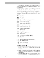
Page 16: ...wer heating elements Conventional cooking Upper heating element only Lower heating element only Inner grill heating element Radiant grill Full grill heating element Radiant grill Full grill heating el...

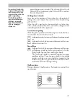
Page 17: ...en turned on Indicates that both the top external element and the inner element are turned on Fan grilling Indicates that both the top external element and the inner grill element as well as the fan a...

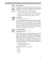
Page 18: ...C 250 C Moderate oven 180 C This mode uses upper and lower heating elements to cook a single dish Cooking is possible on one shelf position only and food should be placed towards the centre of the ov...

Page 19: ...s mode will also give an effect similar to spit roasting especially for poultry or pork where a crisp skin is desired It is also ideal for foods which require additional browning such as au gratin or...

Page 20: ...the oven door during operation turn to a non fan function to minimise heat loss If necessary to cover food with foil or baking paper whilst cooking in fan mode ensure that the foil or paper is firmly...

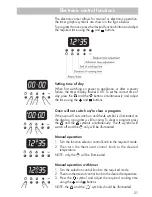
Page 21: ...f the oven will not switch on and the symbol is illuminated on the display a program is still running To clear a program press the and the symbols simultaneously The ssymbol will switch off and the on...

Page 22: ...n this mode the oven is programmed to start and stop at a predetermined time 1 Press the symbol and using the and buttons adjust the time you wish the cooking to stop 2 Press the symbol and adjusting...

Page 23: ...f 2 3 2 3 2 or 3 4 or 5 shelf or 4 or 4 Type of cooking Roast lamb beef poultry Steak Chops and sausages Hamburgers Chicken fillets Chicken pieces Whole fish Fish fillets Casseroles Bread Cakes Scones...

Page 24: ...dvice Food cooking too quickly Oven temperature set too high Check oven chart lower temperature Pan used larger than recipe required Allow less time or use smaller pan Thermostat too high faulty Phone...

Page 25: ...ficient cooking time Increase cooking time Sides too high on cake tin Use smaller tin Incorrect position Refer to cooking chart Tray too large Allow 5 cm airflow around items Cake cracking on top Oven...

Page 26: ...Never use abrasive products sharp objects steel scouring pads knives etc to remove stubborn food remains from the hob surface trivets burners and oven interior Do not allow acidic products such as vi...

Page 27: ...t from its mounting as shown in figure below right 5 To replace the door fit the hinges on their mountings and lower the levers 6 Close the door Use a window cleaner to clean the exterior glass panel...

Page 28: ...s hinge upstand bracket 5 Lift hob at rear and slide out of position To replace gas control valves or gas manifold Pull cooker forwards to gain access to the rear of the cooker and follow procedure ab...

Page 29: ...of the cooker and feed through the access hole in the rear oven wall Clip bulbs into the retaining brackets 7 Reconnect electronic connectors 8 Reassemble in reverse order To remove side panels Pull...

Page 30: ...the electronic spark electrode 4 Reassemble the cooker in the reverse order To replace the under hob cooling fan Follow procedure described as per the heading Access to under hob area 1 Remove cooker...

Page 31: ...ce 3 Remove the inner glass panel as per the heading To replace the inner glass panel 4 Undo 3 phillips head screws along the bottom of the door to release the inner door panel and remove 5 Undo 2 phi...

Page 32: ...re described as per the heading To replace the gas control valves and gas manifold 1 Undo electronic connectors Mark connectors to ensure correct reconnection positions 2 Slide electronic programmer f...

Page 33: ...Disconnect electric wiring to the element at the rear of the oven 3 Lift off oven door as per heading to remove oven door 4 Remove 2 phillips head screws securing oven floor at front 5 Slide oven floo...

Page 34: ...tat m Brown c Light blue v Violet r Red a Orange b Blue n Black g Yellow P Pushbutton 1a One of the contacts of the relay of the programmer interrupting wire L L Line brown wire the other one is the c...

Page 35: ...Part no W1885 Revision D 2006...

Reviews: