background image

OBD & Battery Analysis Scanner

- 34 -

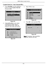
Complete Data Set - Record All PIDs (continued)

4. From

Select Memory,

have

the passenger select a memory

location, then press

OK.

5. After the passenger determines

that recording is finished, stop

driving. Data can be viewed

immediately or saved to view later.

Figure 90

Note:

An asterisk (*) next to a

location indicates a recording already

exists there. Selecting this location

will overwrite it with new data.

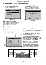
Playback Data

Note:

If necessary, have a qualified

technician interpret the data.
1. Scroll Left/Right/Up/Down

to view Playback Data:

Frame 6 of 46

in Row 36

P…la.yback

6/46 Frame

36

DTC_CNT

0

FUELSYS1

0L

FUELSYS2

--

?

LOAD_PCT(%)

0.0

Figure 91

Interpret Playback Data:

In the grid below, each row contains frames

of PID values shown in

Figure 93.

In this example, there are 36 PIDs (rows)

with 46 frames in each row.
The highlighted frame shows frame

6 of 46 for Row 36.

This particular frame

shows that the PID for

Short Term Fuel

Trim Bank 1

has a value of

99.2%.

Each frame shows a value at the

time of capture, making it possible

Row

36

ECT(

°

F)

-40

SHRTFT1(%)

99.2

Figure 92

to see how the values of individual

PIDs fluctuate over the course of the

recording by scrolling across rows.

3/46

34

4/46

34

5/46

34

Frame 6/46

Row 34 - LOAD PCT(%)

0.0

7/46

34

8/46

34

9/46

34

3/46

35

4/46

35

5/46

35

Frame 6/46

Row 35 - ECT(° F)

- 40

7/46

35

8/46

35

9/46

35

3/46

36

4/46

36

5/46

36

Frame 6/46

Row 36 - SHRTFT1(%)

99.2

7/46

36

8/46

36

9/46

36

Figure 93: Interpreting Playback Data

?

Location #2

Location #3

Select Memory

1/3

Location #1

*

NO

YES

Recording Done!

Playback data?

Record Data

Summary of Contents for KM301

Page 1: ...OBDII CAN SCAN TOOL 1 ...

Page 2: ... 31 Record Live PID Data 33 Playback Live PID Data 36 View Freeze Frame Data 37 I M Readiness 37 02 Monitor Test 38 On Board Monitor Test 39 Component Test 40 Mode 09 Vehicle Information 41 Modules Present 42 Print Data 43 Update 44 WARNING SYMBOLS AND DEFINITIONS This is the safety alert symbol It is used to alert you to potential personal injury hazards Obey all safety messages that follow this ...

Page 3: ...il distributor cap ignition wires and spark plugs These components create hazardous voltages when the engine is running 7 Put the transmission in PARK for automatic transmission or NEUTRAL for manual transmission and make sure the parking brake is engaged 8 Keep a fire extinguisher suitable for gasoline chemical electrical fires nearby 9 Don t connect or disconnect any test equipment while the ign...

Page 4: ...ry Analysis Scanner 2 Setup Before Use Read the ENTIRE IMPORTANT SAFETY INFORMATION section at the beginning of this document including all text under subheadings therein before set up or use Functions Figure 1 ...

Page 5: ... no DTCs are present 6 Cancel Go Cancels a selection from a menu or returns to the previous screen 7 Left Button Moves to previous screen if information covers more than one screen 8 Help Button View detailed information if available 9 USB Connector Connects the Scan Tool to a PC for updating software and printing 10 I M Button Quick checks emissions test readiness and Drive Cycle verification 11 ...

Page 6: ...g Note The Scan Tool is powered by the vehicle s battery 1 Turn the engine and ignition OFF 2 Connect the OBD II Cable to the Scan Tool 3 Connect the other end of the Cable to the 16 cavity DLC The DLC is normally located under the dashboard on the driver s side Refer to vehicle s owner s manual for location of DLC Figure 2 DLC 4 Turn the vehicle s ignition ON with the engine OFF Note If Linking E...

Page 7: ...mp for 2 3 minutes and then measure it when the voltage drops back to the normal value 3 Do not store or use this product in direct sunlight or expose it to high temperature and humidity otherwise it may cause deformation or damage 4 Available battery standards 1 Cold start rating ampere range Measure Standard Measure Range CCA 100 2000 BCI 100 2000 CA 100 2000 MCA 100 2000 JIS 26A17 245H52 DIN 10...

Page 8: ...ew Data 4 Print Data Figure5 3 Use Up Down button to select Battery Test then press OK Battery Test 1 3 1 Battery Test 2 Cranking Test 3 Charging Test Figure6 4 The screen automatically displays the following information follow the prompts 1 If battery just completes charging please turn on vehicle headlights 2 Keep the headlights on for 30 seconds 3 Turn off the headlights 4 Press OK to start tes...

Page 9: ...10 8 If the battery power is low the screen will automatically prompt battery power is low continue press OK to continue if the battery power is normal the screen will directly display Testing Battery power is low Continue Figure11 9 Screen auto prompt Testing Please wait for about 3 seconds Battery Test Testing Figure12 10 Screen displays battery test result as follows Press ESC to exit Battery T...

Page 10: ...ge 80 12 68V Internal R 18 1mΩ Rated 500A REPLACE Figure16 The battery is near to or already reached the end of the using life replace battery otherwise bigger danger will be followed 4 Bad Cell Replace Battery Test Healthy 0 0CCA Charge 80 10 64V Internal R 45 2mΩ Rated 500A BAD CELL REPLACE Figure17 Battery interior damaged bad cell or short circuit replace battery 5 Charge Retest Battery Test H...

Page 11: ...uently used value for starting battery at 0 F 18 C BCI Battery Council International standard CA Cranking Amps standard effective starting current value at 0 C MCA Marine Cranking Amps standard effective starting current value at 0 C JIS Japan Industrial Standard displayed on the battery as combination of the numbers and letters e g 55D23 80D26 DIN German Auto Industry Committee Standard IEC Inter...

Page 12: ... complete the cranking test and display the result Cranking Test Start Engine Figure22 Cranking Test RPM Detected Figure23 5 Normally cranking voltage value lower than 9 6V is regarded as abnormal and it is ENTER if it is higher than 9 6V Test result of the tester includes actual cranking voltage and actual cranking time Cranking Test TIME 780ms CRANKING NORMAL 10 13V Figure24 6 When cranking test...

Page 13: ...ster will do the following tests in a sequence 3 Ripple Test Ripple Test _______________________ 0mV 11 97V Figure27 For ripple test tester will display the real time ripple and meanwhile shows ripple volt and charging volt values at the bottom line It takes approx 6 seconds for the rippletest 4 After the ripple test tester will automatically start the loaded voltage test It takes 3 seconds Chargi...

Page 14: ...off Check the connection between generator and battery is normal or not If both of the drive belt and the connection are in good condition follow the manufacturer s suggestion to eliminate generator fault 3 Charging Volt High Generator output volt is high Since most of the vehicle generators are using internal regulator the generator assembly has to be replaced Some old style cars are using extern...

Page 15: ...ss OK Input Ah Value 50Ah Please input the A HR value in the lable of the battery Figure33 3 If the battery power is low the screen will automatically prompt Battery power is low Continue then press OK to continue Battery power is low Continue Figure34 4 Screen auto prompt Testing Please wait for about 3 seconds Battery Test Testing Figure35 5 Screen displays battery test result as follows Press E...

Page 16: ... from the internet 1 Go to www kzyee com 2 Search for KM301 3 Download Installsoftware 4 Download KM301 BatteryTestPrint 2 Connect the tool to the computer via the USB cable 3 Install the KM301 BatteryTestPrint exe and select default 4 After installation open the KM301 BatteryTestPrint on the desktop 5 Select print If there are some data history in print software please kindly press the Clean butt...

Page 17: ...Printing data Print Data Printing Figure40 8 Once the data is transferred to the computer the print software will show data to be print Battery Test Healthy 85 410A CCA Charge 0 11 97V Internal R 6 61mΩ Rated 400A GOOD RECHARGE Figure41 ...

Page 18: ...OBD Battery Analysis Scanner 16 ...

Page 19: ...le conditions Vehicle Coverage This Scan Tool is designed to work with all OBD II compliant vehicles including those equipped with a CAN bus OBD II was installed in some 1994 and 1995 model year gasoline vehicles When a problem is detected the OBD II system turns on a warning lamp MIL on the vehicle instrument panel to alert the driver typically by the phrase of Check Engine or Service Engine Soon...

Page 20: ...at must occur during a Drive Cycle to cause the I M Monitors to run and complete their diagnostic tests MIL Malfunction Indicator Lamp The vehicle s Check Engine warning light that activates when a DTC is stored DTC Diagnostic Trouble Code A code stored in the computer system s memory which helps to identify the fault condition that is causing the MIL to activate Freeze Frame Data Operating condit...

Page 21: ...ne Monitors Continuous MIS Misfire FUEL Fuel System CCM Comprehensive Components Non Continuous Monitors that require specific operating conditions to be met during a Drive Cycle in order for the Monitors to run their testing sequences Note Not all Monitors are supported by all vehicles Non Continuous CAT Catalyst HCAT Heated Catalyst EVAP Evaporative System AIR Secondary Air System O2S Oxygen Sen...

Page 22: ...ata and Readiness Monitors Mode 05 Oxygen Sensor Test Results This mode displays the oxygen sensor monitor screen and the test results gathered about the oxygen sensor Mode 06 Non Continuously Monitored Systems test results There are typically a minimum value a maximum value and a current value for each non continuous monitor This data is optional and it is defined by a given vehicle maker if it s...

Page 23: ...ed by the OBD II system after repairs are made and a set number of Driving Cycles have been completed Example P0212 Injector Circuit Open Cylinder 12 Systems B Body C Chassis P Powertrain U Network Code Types 0 Generic 1 Manufacturer Specific 2 Generic Powertrain Manufacturer Specific 3 Generic Powertrain Manufacturer Specific Sub Systems 1 Fuel and Air Metering 2 Fuel and Air Metering injector ci...

Page 24: ...o operate the Scan Tool System Setup 1 7 Language Configure Monitors Unit of Measure Key Beep Set Status Beep Set Tool Self test Update Mode Main Menu Figure 51 Figure52 Set Language 1 From System Setup use the Up Down button to select Language then press OK 2 Select desired language then press OK Figure53 o English o Español o Français Language 1 3 ...

Page 25: ...orted on the vehicle see I M Readiness Quick Check on page 26 Figure54 2 Select a configuration then press OK a Spark IGN Required Mon For gasoline engines b Compression IGN Required Mon For diesel engines c Allowed INC Monitors to Set how many incomplete Monitors are acceptable d Reset Factory Default 3 Custom Data Set screen shows which buttons can be used to configure the monitors Press any but...
Page 26: ...Pressed 1 From System Setup use the Up Down button to select Key Beep Set then press OK 2 Select Beep ON or Beep OFF then press OK Figure59 Status Beep Set Control Notification Sounds 1 From System Setup use theUp Down button to select Status Beep Set then press OK 2 Select Beep ON or Beep OFF then press OK Figure60 Unit of Measure o English o Metric o Beep ON o Beep OFF Key Beep Set 1 2 Status Be...

Page 27: ...button to select Keyboard Test then press OK 2 Press each button to make sure they are functioning properly If functioning properly the correct name for each button will display after the word key 3 Press ESC twice to exit the test LED Test Figure 62 1 From Tool Self test use the Up Down button to select LED Test then press OK 2 Toverify that the LEDs are functioning properly select each LED then ...

Page 28: ...y Keyboard LED Interpretations 1 Green LED Ready Indicates that engine systems are running normally and no pending DTCs are present 2 Yellow LED Might be Ready Indicates there are pending DTCs or there are Monitors that have not finishing running Perform a Drive Cycle then repeat the test 5 View results and interpret data as described below Figure 64 Note You may need to complete a Drive Cycle bef...

Page 29: ...e examples given herein 3 Control Module will display In Figure 66 below the example vehicle uses the CAN Protocol and has the following Control Modules 7E8 PCM ID 7E9 TCM ID See Control Modules on page 42 for more information Main Menu 2 System Status will display momentarily Figure 66 4 Press OK to go to Diagnostic Menu Figure 65 Figure 67 Note If vehicle is 2008 or newer the 02 Monitor Test wil...

Page 30: ...0 and is required on all 2012 and newer vehicles 2 If there are no DTCs the message No codes are stored in the module will appear Figure 68 3 View the DTC DTC Control Module P0122 2 8 10 Generic Throttle Pedal Position Sensor Switch A Circuit Low DTC Description Figure 69 4 See DTC Lookup on page 29 to view likely causes for DTCs Note To view operational data stored when the DTC was stored see Vie...

Page 31: ...ng the buttonsto highlight and change digits then press OK Left Right Change digit OK Confirm ESC Exit Figure 71 Figure 72 2 Press the button to viewlikely causes for the DTC 3 If a DTC is manufacturer specific a screen will prompt the choice of vehicle make 4 If a DTC is not found the Scan Tool will refer you to the vehicle s owner s manual Note DTC definitions can also be found online 1 1 P0212 ...

Page 32: ...leted 1 Turn the vehicle s ignition ON with the engine OFF 2 From Diagnostic Menu use the Up Down button to select Erase Codes then press OK 3 Choose whether or not to erase codes Figure 74 4 When DTCs have been erased the following message will appear Figure 73 Figure 75 Note Erasing codes will reset the Monitors to incomplete status A Drive Cycle will need to be completed before performing an Em...

Page 33: ... use the Up Down button to select Complete Data Set then press OK 3 Press to view the PID s full name Figure 80 Figure 78 2 View all PIDs and theirparameters using the Up and Down Buttons Live Data 6 DTC_CNT 0 FUELSYS1 FUELSYS2 LOAD_PCT 0L 0 0 ECT F 40 0 SHRTFT1 0 0 LONGFT1 0 8 Figure 79 4 Press OK to view a graph if available Figure 81 Note If necessary have a qualified technician interpret the d...

Page 34: ... deselect PIDs Press any button to move to the next screen Figure 84 4 Press OK to view selected PIDs Figure 83 Figure 85 Note If necessary have a qualified technician Interpret the data Custom Data Set Select Deselect Select Deselect all OK Confirm ESC Cancel Press any key to con 001 DTC_CNT FUELSYS1 FUELSYS2 LOAD_PCT ECT SHRTFT1 LONGFTI Custom Data Set 4 20 0 DTC_CNT Live Data 1 Complete Data Se...

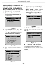
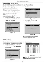
Page 35: ...he Scan Tool while driving the vehicle Have a passenger operate the Scan Tool 1 Start the vehicle and begin driving 2 From Record Data have the passenger select Complete Data Set then press OK 3 Have the passenger select a Trigger Mode Manual Trigger Recording willbegin after memory location is selected DTC Trigger Recording will begin when a DTC is detected Complete Data Set Custom Data Set Unit ...

Page 36: ...k Data In the grid below each row contains frames of PID values shown in Figure 93 In this example there are 36 PIDs rows with 46 frames in each row The highlighted frame shows frame 6 of 46 for Row 36 This particular frame shows that the PID for Short Term Fuel Trim Bank 1 has a value of 99 2 Each frame shows a value at the time of capture making it possible Row 36 ECT F 40 SHRTFT1 99 2 Figure 92...

Page 37: ...ed to select deselect PIDs Have the passenger press any button to move to the next screen Figure 97 6 From Select Memory have the passenger select a memory location then press OK Figure 95 4 Have the passenger select deselect PIDs Figure 98 Note An asterisk next to a location indicates a recording already exists there Selecting this location will overwrite it with new data 001 DTC_CNT FUELSYS1 FUE...

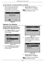
Page 38: ...erpreted by a qualified technician 1 From Diagnostic Menu use theUp Down button to select Live Data then press OK Figure 101 3 From Select Memory use the Up Down button to select a memory location marked with an asterisk then press OK Figure 100 2 From Live Data use the Up Down button to select Playback Data then press OK Figure 102 4 Interpret data according to Playback Data on page 34 Note If ne...

Page 39: ... I M Readiness Check emissions readiness prior to having a vehicle inspected for a state Emissions Test 1 From Diagnostic Menu use the Up Down button to select I M Readiness then press OK Figure 105 Note If necessary have a qualified technician Interpret the data 2 View test results Figure 106 Figure 107 Note See I M Readiness Quick Check on page 26 to interpret data Read Codes Erase Codes Live Da...

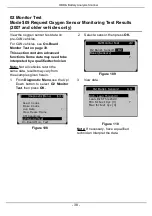
Page 40: ...turn the same data results may vary from the examples given herein 1 From Diagnostic Menu use the Up Down button to select O2 Monitor Test then press OK 2 Select a sensor then press OK Figure 109 3 View data Figure 108 Figure 110 Note If necessary have a qualified technician Interpret the data O2 Bank1 Sensor1 O2 Bank1 Sensor2 O2 Monitor Test 2 2 Lean Rich Threshd V Min for text Cyc V Max for text...

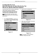
Page 41: ...gnostic Menu use the Up Down button to select On Board Mon Test then press OK 2 Select vehicle manufacturer Figure 112 3 Select and view Monitors their tests and results as needed On Board Mon Test 1 10 A F Sensor Bank Sensor 1 H02S Bank Sensor 2 Catalyst Mon Bank 1 EVAP EGR Heater Mon B1S2 Misfire Misfire Figure 111 Figure 113 Note If necessary have a qualified technician Interpret the data Vehic...

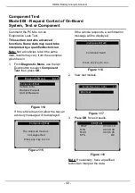
Page 42: ...t Test then press OK If the vehicle responds a confirmation message will be displayed Figure 116 2 View test module Figure 114 If the vehicle does not allow the test an advisory message will be displayed Figure 117 3 Press OK for test results Component Test The selected mode is not supported Press any key to con Figure 115 Figure 118 Note If necessary have a qualified technician Interpret the data...

Page 43: ... Down button to select Vehicle ID Number then press OK Vehicle ID Number Calibration ID Cal Verf Number Vehicle Info 1 3 Figure 120 3 View Vehicle ID Number Figure 123 6 From Vehicle Info use the Up Down button to select Cal Verf Number then press OK Vehicle Info 3 3 Vehicle ID Number Calibration ID Cal Verf Number Figure 124 7 View CVN information Vehicle ID Number VIN LSVGU49JX92545482 Figure 12...

Page 44: ...enu use the Up Down button to selectModules Present then press OK 2 Control Module will display 3 In Figure 127 below the example vehicle uses a CAN bus and has the followingODB Control Module IDs and Protocols ID Control Module Communication Protocol 7E8 Powertrain CAN bus 7E9 Transmission CAN bus Diagnostic Menu 10 11 Component Test Vehicle Info Modules Present Unit of Measure Protocol CAN STD F...

Page 45: ...ta as needed Figure 129 Note If necessary have a qualified technician Interpret the data Figure 128 Main Menu Print Data 1 Connect the Scan Toolto the computer with the supplied USB Cable 2 From the Main Menu use theUp Down Left Right button to select Print Data then press OK Figure 131 3 Follow instructions on the Scan Tooland thecomputer Figure 130 Main Menu Live Data I M Readiness Modules Prese...

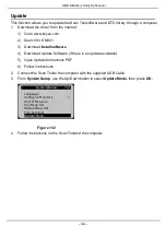
Page 46: ...4 Download Update Software if there is an update available 5 Open Update Instructions PDF 6 Follow instructions 2 Connect the Scan Toolto the computer with the supplied USB Cable 3 From System Setup use the Up Down button to select Update Mode then press OK Figure 132 4 Follow instructions on the Scan Tooland the computer System Setup 7 7 Language Configure Monitors Unit of Measure Key Beep Set St...

Page 47: ...OBD Battery Analysis Scanner 45 ...

Page 48: ...or consequential damages so the above limitation of exclusion may not apply to you THIS WARRANTY IS EXPRESSLY IN LIEU OF ALL OTHER WARRANTIES EXPRESS OR IMPLIED INCLUDING THE WARRANTIES OF MERCHANTABILITY AND FITNESS To take advantage of this warranty the product or part must be returned to us with transportation charges prepaid Proof of purchase date and an explanation of the complaint must accom...

Reviews: