background image


12 

details, see sections 6.2 and 6.3. 


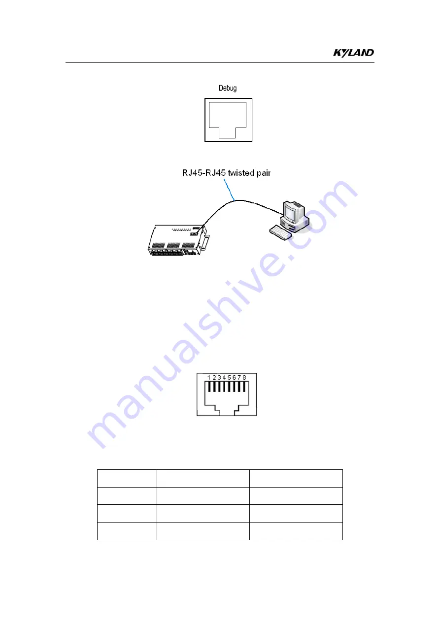
Figure 17 Debug Port 


Figure 18 Cable Connection of Debug Port 

The debug port is self-adaptive. It can automatically configure itself to work 

in 10M or 100M state, full or half duplex mode. The port can also adapt to 

MDI  or  MDI-X  connection  automatically.  You  can  connect  the  port  to  a 

terminal or network device with a straight-through or cross-over cable. 

Figure 19 shows the pin numbers of the debug port. 


Figure 19 Pin Numbers 

Table 5 lists the pin definitions of the debug port. 

Table 5 Pin Definitions of Debug Port 

Pin 

MDI-X Signal 

MDI Signal 

Receive Data+ (RD+) 

Transmit Data+ (TD+) 

Receive Data- (RD-) 

Transmit Data- (TD-) 

Transmit Data+ (TD+) 

Receive Data+ (RD+) 

Summary of Contents for SICOM3016BA-4GX-12S/M

Page 1: ...ICOM3016BA Industrial Ethernet Switch Hardware Installation Manual Kyland Technology Co Ltd Publication Date Apr 2013 Version V1 1 FAX 86 10 88796678 Website http www kyland com E mail support kyland com ...

Page 2: ...pdated as possible This document is not guaranteed to be error free and we reserve the right to amend it without notice to users All rights reserved No part of this documentation may be excerpted reproduced translated annotated or duplicated in any form or by any means without the prior written permission of KYLAND Corporation Copyright 2013 Kyland Technology Co Ltd ...

Page 3: ... the cable which may cause a fire risk Power connectors and other equipment connectors should be firmly interconnected and checked frequently Do not repair the equipment by yourself unless it is clearly specified in the manual Please keep the equipment clean if necessary wipe the equipment with soft cotton cloth In the following cases please immediately shut down your power supply and contact your...

Page 4: ...Cable Connection 6 4 110 100Base T X Port 6 4 2100Base FX Port 8 4 31000Base X SFP Port 8 4 4Console Port 10 4 5Debug Port 11 4 6Power Terminal Block 13 4 7Grounding 15 5 LEDs 15 6 Switch Access 16 6 1Access through Console Port 16 6 2Access through Telnet 18 6 3Access through Web 19 7 Product Configuration Information 19 8 Basic Features and Specifications 21 ...

Page 5: ...b and SNMP based network management software SICOM3016BA has two forms integrated device and bare board An integrated device supports panel mounting while a bare board can be installed in another device SICOM3016BA provides diversified ports including 1000Base X SFP 100Base FX and 10 100Base T X ports 2 Structure and Interface 2 1 Front Panel Table 9 and Table 10 list the products models of SICOM3...

Page 6: ...se T X port 3 10 100Base T X RJ45 port speed LED 4 10 100Base T X RJ45 port Link ACT LED 5 GX1 GX4 1000Base X SFP port 6 Grounding screw 7 Mounting ear 2 2 Top Panel Figure 2 Top Panel Table 2 Top Panel of SICOM3016BA No Identifier Description 1 PWR Power LED 2 Alarm Alarm LED 3 Run Running LED 1 2 3 4 5 6 7 8 9 ...

Page 7: ...ED 6 ACAlarm Power terminal block 7 Console Console port 8 Debug Debug port 9 Mounting ear 3 Mounting 3 1 Dimension Drawing SICOM3016BA Integrated Device unit mm Figure 3 SICOM3016BA Integrated Device 1 2 3 4 5 6 8 9 10 11 12 284 19 44 5 5 12 5 88 64 265 140 244 ...

Page 8: ... follows Panel Mounting Integrated Device Step 1 Select the mounting position on a wall or an inner wall of a cabinet for SICOM3016BA and guarantee adequate space for it Step 2 Punch four holes in the selected position according to the dimensions of SICOM3016BA Insert four screws into the four holes respectively and turn the screws with a screwdriver until about a 5mm distance is left between each...

Page 9: ...e 5 Figure 5 Panel Mounting Panel Dismounting Integrated Device Step 1 Loosen the four screws with a screwdriver Move the device to the left or right until the screws are located in the middle of the four mounting holes on the mounting ears Then make the screws pass through the mounting holes In this way you can remove the device from the wall or inner wall of the cabinet Step 2 Loosen the screws ...

Page 10: ...lf to work in 10M or 100M state full or half duplex mode The port can also adapt to MDI or MDI X connection automatically You can connect the port to a terminal or network device with a straight through or cross over cable Figure 7 shows the pin numbers of the 10 100Base T X RJ45 port 8 7 6 5 4 3 2 1 Figure 7 RJ45 Port Table 3 lists the pin definitions of the 10 100Base T X RJ45 port ...

Page 11: ...a RD 6 Transmit Data TD Receive Data RD 4 5 7 8 Unused Unused Note and indicate level polarities Wiring Sequence Figure 8 Connection Using Straight through Cable Figure 9 Connection Using Cross over Cable Note The color of the cable for RJ45 connector meets the 568B standard 1 orange and white 2 orange 3 green and white 4 blue 5 blue and white 6 green 7 brown and white and 8 brown ...

Page 12: ... RX receive port of Switch A to the TX transmit port of Switch B Figure 10 100Base FX Cable Connection Caution The device uses laser to transmit signals in fibers The laser meets the requirements of level 1 laser products Routine operation is not harmful to your eyes but do not look directly at the fiber port when the device is powered on 4 3 1000Base X SFP Port To use 1000Base X SFP port you need...

Page 13: ...nsert the two connectors in one end of optical fiber into gigabit SFP module and those in the other end of the optical fiber into the SFP module of another switch 2 Check the corresponding port Link ACT indicator in the front panel If the indicator blinks the link is connected If the indicator is off the link is not connected This may be caused by incorrect connection of the TX and RX ports In thi...

Page 14: ...f such a short fiber is used the module will be burned 4 4 Console Port There is a console port on the top panel of the switch as shown in Figure 14 Connect the 9 pin serial port of a PC to the console port of the switch with an RJ45 DB9 console cable You can configure maintain and manage the switch by running the Hyper Terminal in the Windows OS of the computer Figure 14 Console Port RJ45 DB9 Con...

Page 15: ...ransmit Data TXD 5 GND 1 4 6 7 8 9 Unused Figure 16 shows the wiring sequence of the RJ45 DB9 console cable Figure 16 Wiring Sequence of Console Cable 4 5 Debug Port The debug port as shown in Figure 17 is on the top panel The port is equipped with RJ45 connector You can connect the port to the network port of a PC with an RJ45 RJ45 twisted pair as shown in Figure 18 Then you can manage and config...

Page 16: ...adapt to MDI or MDI X connection automatically You can connect the port to a terminal or network device with a straight through or cross over cable Figure 19 shows the pin numbers of the debug port Figure 19 Pin Numbers Table 5 lists the pin definitions of the debug port Table 5 Pin Definitions of Debug Port Pin MDI X Signal MDI Signal 1 Receive Data RD Transmit Data TD 2 Receive Data RD Transmit ...

Page 17: ...r RJ45 connector meets the 568B standard 1 orange and white 2 orange 3 green and white 4 blue 5 blue and white 6 green 7 brown and white and 8 brown 4 6 Power Terminal Block SICOM3016BA adopts 6 pin 5 08mm spacing plug in terminal block You need to connect the power cable to the terminal block to provide power and AC power alarm signals for the device Note 0 75mm2 Cross sectional area of the power...

Page 18: ...indicates AC power supply while low level input indicates alarm battery power supply The AC DC power supply status is displayed on the Web network management interface Wiring and Mounting Step 1 Remove the power terminal block from the switch Step 2 Insert the power cable into the power terminal block according to Table 6 to fix the power cable Step 3 Insert the terminal with the connected cable i...

Page 19: ... 5 5 LEDs Table 7 lists the descriptions of SICOM3016BA LEDs Table 7 LEDs LED State Description Running LED Run On The CPU operates abnormally or the device is starting up Blinking 1Hz The CPU operates properly Off The CPU does not start up Alarm LED Alarm On An alarm occurs Off No alarm occurs Power LED PWR On The power is connected and operates properly Off The power is not connected or operates...

Page 20: ...ve port connection 1000Base X SFP Port LED Link ACT On Effective port connection Blinking Ongoing network activities Off No effective port connection 6 Switch Access You can access the switch in any of the following ways 6 1 Access through Console Port Step 1 Connect the 9 pin serial port of a PC to the console port of the switch with an RJ45 DB9 console cable Step 2 Open the Hyper Terminal in the...

Page 21: ...the COM port in use You can view the port in use in Device Manager as shown in Figure 25 Figure 25 Selecting a Serial Port Step 5 Set port parameters Bits per second 9600 Data bits 8 Parity None Stop bits 1 and Flow control None as shown in Figure 26 ...

Page 22: ...ersion Query the version of the switch Management view SWITCH reboot Restart the switch Management view SWITCH load default Restore the factory default settings excluding the IP address Management view SWITCH config terminal Enter the configuration view 6 2 Access through Telnet Step 1 Connect the network port of a PC to the 10 100Base T X port or debug port of the switch with an RJ45 RJ45 network...

Page 23: ...terface is displayed You can log in to the Web UI by using default user name admin and password 123 Note IE8 0 or a later version is recommended 7 Product Configuration Information Table 9 and Table 10 list the models supported by SICOM3016BA Table 9 SICOM3016BA Configuration Integrated Device Model Interface Power SICOM3016BA 4GX 12S M Four 1000Base X SFP ports twelve 100Base FX ports SM MM FC ST...

Page 24: ...ing on the PCB C is added to the names before the identifiers for ports Table 10 SICOM3016BA Configuration Bare Board Model Interface Power SICOM3016BA EM C 4GX 12S M Bare board with conformal coating four 1000Base X SFP ports twelve 100Base FX ports SM MM FC ST SC connector 5DC 12DC redundant SICOM3016BA EM C 4GX 8S M 4T Bare board with conformal coating four 1000Base X SFP ports eight 100Base FX...

Page 25: ... 55 1000Base X port multi mode LC connector 850nm center wavelength CWL 550m transmission distance IGSFP S LX LC 1310 10 1000Base X port single mode LC connector 1310nm center wavelength CWL 10km transmission distance IGSFP S LH LC 1310 40 1000Base X port single mode LC connector 1310nm center wavelength CWL 40km transmission distance IGSFP S ZX LC 1550 80 1000Base X port single mode LC connector ...

Page 26: ...imensions W H D 284mm 44mm 140mm integrated device 235mm 130mm bare board W D Weight 1 5kg Environmental Limits Operating temperature 40 to 85 Storage temperature 40 to 85 Ambient relative humidity 5 to 95 non condensing MTBF 329 032 hours Warranty 5 years For more information about KYLAND products please visit our website http www kyland com ...

Reviews: