background image

Connection 

13


  How to Connect the SFP Optical Module 

Insert the SFP optical module into the SFP slot in the switch, and then insert the fibers into the 

TX port and RX port of the SFP module. 


Figure 17 Connecting the SFP Optical Module 

Identify the RX port and TX port of an SFP optical module: 

1. Insert the two connectors in one end of two fibers into the SFP module, and those in the other 

end into the peer module. 

2. View the corresponding connection status LED: 

If the LED is on, the connection is correct. If the LED is off, the link is not connected. This may 

be caused by incorrect connection of the TX and RX ports. In this case, swop the two 

connectors at one end of the fibers. 


Caution:


  The device uses laser to transmit signals in fibers. The laser meets the requirements of level 1 laser 

products. Routine operation is not harmful to your eyes, but do not look directly at the fiber port when 

the device is powered on. 

  If the defined transmission distance of an SFP module is longer than 60km, do not use a short fiber 

(<20km) for connection. If such a short fiber is used, the module will be burned. 

4.3.2  Gigabit SFP Electrical Module 


Figure 18 Gigabit SFP Electrical Module 


Summary of Contents for KIEN1009

Page 1: ...Industrial Ethernet Switch Hardware Installation Manual Kyland Technology Co Ltd Publication Date Mar 2013 Version V1 0 FAX 86 10 88796678 Website http www kyland com E mail support kyland com No 1 12 02 1049 0 ...

Page 2: ...ated as possible This document is not guaranteed to be error free and we reserve the right to amend it without notice to users All rights reserved No part of this documentation may be excerpted reproduced translated annotated or duplicated in any form or by any means without the prior written permission of KYLAND Corporation Copyright 2013 Kyland Technology Co Ltd ...

Page 3: ...e other protective measures when operating the device Avoid any exposed metal wires because they may be oxidized or electrified Install the device in accordance with related national and local regulations Before power on make sure the power supply is within the allowed range of the device High voltage may damage the device Power connectors and other connectors should be firmly interconnected Do no...

Page 4: ...ntal pollution In the following cases please immediately shut down your power supply and contact your Kyland representative Water gets into the equipment Equipment damage or shell damage Equipment operation or performance has abnormally changed The equipment emits odor smoke or abnormal noise ...

Page 5: ...d Steps 7 3 2 1DIN Rail Mounting 7 3 2 2Panel Mounting 8 4 Connection 10 4 1 10 100Base T X Ethernet Port 10 4 2 100Base FX Ethernet Port 11 4 3 1000Base X 10 100 1000Base T X SFP Slot 12 4 3 1Gigabit SFP Optical Module 12 4 3 2Gigabit SFP Electrical Module 13 4 4 Grounding 14 4 5 Power Terminal Block 14 5 LEDs 18 6 Basic Features and Specifications 19 ...

Page 6: ...KIEN1009 provides up to six 10 100Base T X Ethernet ports two 100Base FX Ethernet ports and one 1000Base X 10 100 1000Base T X SFP slot gigabit SFP slot Table 1 KIEN1009 Models Model Port Power Supply Remarks Gigabit SFP slot 100Base FX Ethernet port 10 100Base T X Ethernet port KIEN1009 E 8T 8 24DC single power supply Normal temperature range 0 60 KIEN1009 8T 8 12DCW 24DCW redundant power supply ...

Page 7: ...sure switch performance 2 1 Front Panel Front Panel of KIEN1009 E 8T Figure 1 Front Panel of KIEN1009 E 8T Table 2 Description of the Front Panel of KIEN1009 E 8T No Identifier Description 1 PWR Power LED 2 1 8 Eight 10 100Base T X Ethernet ports 3 10 100Base T X Ethernet port speed LED yellow 4 10 100Base T X Ethernet port connection status LED green ...

Page 8: ...KIEN1009 8T Table 3 Description of the Front Panel of KIEN1009 8T No Identifier Description 1 PWR1 Power 1 LED 2 PWR2 Power 2 LED 3 1 8 Eight 10 100Base T X Ethernet ports 4 10 100Base T X Ethernet port speed LED yellow 5 10 100Base T X Ethernet port connection status LED green ...

Page 9: ...6T No Identifier Description 1 PWR1 Power 1 LED 2 PWR2 Power 2 LED 3 G1 Gigabit SFP slot connection status LED 4 G1 Gigabit SFP slot 5 7 8 100Base FX Ethernet port connection status LEDs 6 7 8 Two 100Base FX Ethernet ports 7 1 6 Six 10 100Base T X Ethernet ports 8 10 100Base T X Ethernet port speed LED yellow 9 10 100Base T X Ethernet port connection status LED green ...

Page 10: ...ble 5 Description of Top Panel No Identifier Description 1 Power terminal block 2 Power terminal block 3 Grounding screw Note Top panel 1 is applicable to KIEN1009 E 8T Top panel 2 is applicable to KIEN1009 8T KIEN1009 1S M 7T KIEN1009 2S M 6T KIEN1009 3S M 6T and KIEN1009 1GX 2S M 6T ...

Page 11: ...N Rail Mounting unit mm Figure 7 Dimensions for Panel Mounting unit mm Caution As part of the heat dissipation system the switch housing becomes hot during operation Please use caution when coming in contact and avoid covering the switch housing when the switch is running ...

Page 12: ...ower input is within the voltage range of the switch 3 Grounding resistance 5 4 No direct sunlight distant from heat source and areas with strong electromagnetic interference 3 2 1 DIN Rail Mounting Mounting Step 1 Select the mounting position for the device and guarantee adequate space and heat dissipation dimensions 53 6mm 135mm 106 5mm Step 2 Insert the connecting seat onto the top of the DIN r...

Page 13: ...l Dismounting 3 2 2 Panel Mounting Caution Purchase the plate optional for panel mounting Mounting Step 1 Use screws to secure the plate for panel mounting to the rear panel of the device Step 2 Select the mounting position on a wall or inner wall of a cabinet for the device and guarantee adequate space and heat dissipation dimensions 53 6mm 135mm 106 5mm Step 3 Punch four holes in the selected po...

Page 14: ... Pull the device upward until the four screws are in the Ф6 5 positions in the following figure Then remove the plate for panel mounting from the four screws to detach the device from the wall or inner wall of the cabinet Step 2 Loosen the screws completely with a screwdriver Remove them from the wall or inner wall of the cabinet Then remove the plate for panel mounting from the rear panel to comp...

Page 15: ... or network device with a straight through or cross over cable Pin Definition The following figure shows the pin numbers of the 10 100Base T X RJ45 port 8 7 6 5 4 3 2 1 Figure 12 RJ45 Port The following table lists the pin definitions of the 10 100Base T X RJ45 port Table 6 Pin Definitions of 10 100Base T X RJ45 Port Pin MDI X Signal MDI Signal 1 Receive Data RD Transmit Data TD 2 Receive Data RD ...

Page 16: ...ort and RX receive port To enable data transmission between Device A and Device B connect the TX port of Device A to the RX port of Device B and the RX port of Device A to the TX port of Device B The following uses an SC port as an example The wiring sequence of an ST FC port is the same with that of the SC port Figure 14 Connection of 100Base FX Ethernet Port Caution The device uses laser to tran...

Page 17: ...IGSFP S LX LC 1310 10 1000Base X port SM LC 1310nm 10km IGSFP S LH LC 1310 40 1000Base X port SM LC 1310nm 40km IGSFP S ZX LC 1550 80 1000Base X port SM LC 1550nm 80km IGSFP 10 100 1000BASE T RJ45 10 100 1000Base T X port RJ45 4 3 1 Gigabit SFP Optical Module Figure 15 Gigabit SFP Optical Module An SFP optical module is equipped with LC connector and each port consists of a TX transmit port and an...

Page 18: ...onnection is correct If the LED is off the link is not connected This may be caused by incorrect connection of the TX and RX ports In this case swop the two connectors at one end of the fibers Caution The device uses laser to transmit signals in fibers The laser meets the requirements of level 1 laser products Routine operation is not harmful to your eyes but do not look directly at the fiber port...

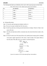
Page 19: ...grounding screw on the top panel for chassis grounding After crimping one end of the grounding cable to a cold pressed terminal secure the end to the grounding screw and connect the other end to the earth firmly Figure 20 Grounding Note Cross sectional area of the chassis grounding cable 2 5mm2 grounding resistance 5 4 5 Power Terminal Block There is a power terminal block on the top panel of the ...

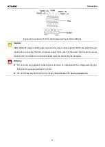
Page 20: ...ug in terminal block Figure 21 3 Pin 5 08mm Spacing Plug in Terminal Block socket The following table lists the pin definitions of the 3 pin 5 08mm spacing plug in terminal block Table 8 Pin Definitions of 3 Pin 5 08mm Spacing Plug in Terminal Block No DC Definition AC Definition 1 PWR PWR L 2 PWR PWR N 3 PGND PGND 5 Pin 5 08mm Spacing Plug in Terminal Block redundant power input The following fig...

Page 21: ...ve the power terminal block from the device Step 3 Insert the power wires into the power terminal block according to Table 8 or Table 9 and secure the wires Step 4 Insert the terminal block with the connected wires into the terminal block socket on the device Step 5 Connect the other end of the power wires to the external power supply system according to the power supply requirements of the device...

Page 22: ...fore connecting the device to power supply make sure that the power input meets the power requirement If connected to an incorrect power input the device may be damaged Warning Do not touch any exposed conducting wire terminal or component with a voltage warning sign because it may cause damage to humans Do not remove any part or plug in or out any connector when the device is powered on ...

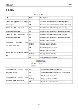
Page 23: ...tes properly Off Power 2 is not connected or operates abnormally 100Base FX Ethernet port connection status LED On Effective port connection Blinking Ongoing network activities Off No effective port connection Gigabit SFP slot connection status LED On Effective port connection Blinking Ongoing network activities Off No effective port connection 10 100Base T X Ethernet port speed LED yellow On 100M...

Page 24: ...MAX Physical Characteristics Housing Aluminum fanless Installation DIN rail mounting and panel mounting Dimensions W H D 53 6mm 135mm 106 5mm excluding connectors DIN rail and plate for panel mounting Weight 0 76Kg Environmental Limits Operating temperature 0 60 KIEN1009 E 8T 40 85 KIEN1009 8T KIEN1009 1S M 7T KIEN1009 2S M 6T KIEN1009 3S M 6T KIEN1009 1GX 2S M 6T Storage temperature 40 85 Ambient...

Reviews: