58
Chapter 7 - TV Measuring Range
106 V3.2
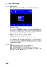
Via the menu item
e-8
the measuring depth can be set back to the default setting 1•10
8
. This
setting is non-volatile. In the operating mode DATAGRABBER and DATALOGGER the
measurement of the bit error rate generally operates with a depth of 1•10
8
bits.
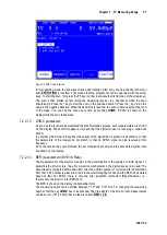
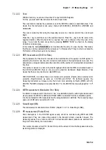
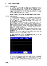
MER measurement (Modulation Error Rate)
7.2.2.1.5
In addition to measurement of the bit error rate, it is established practice within digital transmission
also measures the MER. It is defined in ETR290. MER is calculated from the constellation points.
It is the counterpart to S/N measurement with analog transmission methods. The measuring range
goes up to 40 dB with a resolution of 0.1 dB.
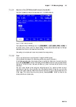
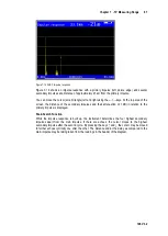
Noise Margin (NM)
7.2.2.1.6
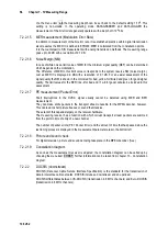
In case of white noise a limit value of MER for the minimum signal quality (QEF) can be determined
which depends on the modulation.
The difference of MER to this limit value corresponds to the system reserve NM (noise margin).
Just as MER it is displayed in dB with a resolution of 0.1 dB. For an easier assessment of the
signal quality the NM is shown in the colors red for bad, yellow for limited and green for good signal
quality. The limit values for the BER (>2e-4 for bad and <1e-6 for good) will also be included in this
assessment.
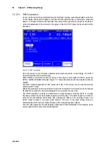
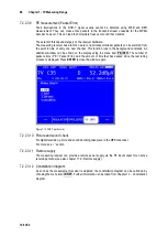
PE measurement (Packet Error)
7.2.2.1.7
Short interruptions in the DVB-C signal usually cannot be detected using MER and BER
measurement.
They can make entire packets in the transport stream unusable for the MPEG decoder, however.
This can lead to short picture freezes or sound that crackles.
The extent of this depends largely on the receiver hardware.
The measuring receiver has a function with which corrupt transport stream packets are summed
from the point in time of entry of a new channel.
The number of packet errors (PE = Packet Error) and the amount of time that has passed since the
last tuning process is displayed in the measurement parameter area in the bottom left.
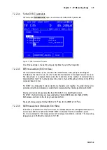
Picture and sound check
7.2.2.1.8
For digital television, picture and sound decoding take place in the MPEG decoder. (See )
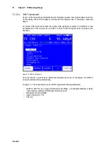
Constellation diagram
7.2.2.1.9
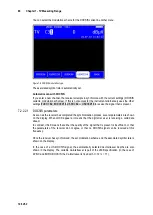
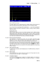
As soon as the measurement receiver is adjusted, the constellation diagram can be called up by
choosing the menu item
CONST
. Further information can be taken from chapter 13 - Constellation
diagram.
7.2.2.2
DOCSIS (downstream)
DOCSIS (Data over Cable Service Interface Specification) is the standard for the transmission of
data in interactive cable networks. DOCSIS includes a downstream and an upstream.
DOCSIS differentiates between US-DOCSIS (transmission in 6 MHz channels) and Euro-DOCSIS
(transmission in 8 MHz channels).

