background image

– 21 –

Summary of Contents for PANTHER

Page 1: ...utterman INC Phone 815 725 9205 Fax 815 725 4429 795 South Larkin Avenue Rockdale Illinois 60436 www kwmgutterman com Manufactured by KWM GUTTERMAN INC OPERATING AND MAINTENANCE TROUBLE SHOOTING GUIDE 5 ...

Page 2: ...ool Assembly and Loading Coil pg 12 13 8 Entrance Guide System pg 14 15 9 Forming Components Guide Bars pg 16 10 Stations 1 thru 7 Factory Settings pg 17 18 11 Lip Forming Box pg 19 21 12 Top 8 Drive Station and Bell Wheel pg 22 23 13A Bead Roller Front Pull Shear Assembly pg 24 13 Bead Roller Guillotine Assembly pg 25 27 14 Gutter Talk pg 28 29 15 Machine Operation Recap Summary pg 30 15A Machine...

Page 3: ...LER VIA CHAIN AND SPROCKETS SHEAR FRONT PULL GUILLOTINE STYLE SHEAR STRAIGHT BLADE GUILLOTINE STYLE SHEAR SPEED APPROXIMATELY 35 PER MINUTE CONTROLS EMERGENCY STOP BUTTON ENTRANCE END MAIN OPERATORS PANEL EXIT END CONSISTING FORWARD AND REVERSE DRUM SWITCH EMERGENCY STOP AND JOG BUTTON ENTRY END MAIN OPERATORS PANEL EXIT END CONSISTING OF START AND PUSH BUTTONS JOG RUN MATERIALS FORMED 11 3 4 TO 1...

Page 4: ...machine 3 Use proper wire gauge extension cord according to table on page 4 4 Loose fitting clothing and or jewelry can be dangerous while operating machine 5 Be sure all operators of this machine are knowledgeable of all safety precautions and operating procedures 6 Before cleaning or making any adjustments to machine Stop machine and disconnect power supply 7 Keeping the machine and its rollers ...

Page 5: ...e consider the gross machine weight including coil 2 Check mounting surface for its integrity and make any repairs necessary prior to installation 3 Bolt machine to the bed of the vehicle using 3 8 dia bolts grade 5 four places Do not draw machine down to an UN flat surface shim as needed to insure four place mounting 3 ...

Page 6: ... switch 2 jog run Green push button start actuator Red push button stop actuator ENTRY OPERATORS PANEL Right side entry end The entry operators panel is located on the O G face side of the machine at the entrance end The entry operators panel consists of Green push button start actuator jog only Emergency Stop power shut off EXTENSION CORD TABLE LENGTH OF CORD WIRE GAUGE COPPER WIRE UP TO 25 12 GA...

Page 7: ...ile feeding a new coil Duplex outlets are provided at the exit end below the drum switch for your convenience When operating your new PANTHER you will need to use an extension cord The table below gives the minimum extension cord wire gauge recommended by the motor manufacturer The cord size needs to be adhered to in order to MAINTAIN WARRANTY ON MOTOR A minimum 4500 watt generator should be used ...

Page 8: ... 6 ...

Page 9: ... 7 ...

Page 10: ... 8 ...

Page 11: ... components Right entrance guide shoe Face guide bar Lip forming box 8 bell wheel D LEFT SIDE The left side of the machine is determined when facing the entrance of the machine The left side of the machine is the back or dead roller side of the gutter Components on the left side Left entrance guide shoe Drive train gears sprockets and chains Back guide bar Bead roller assembly E CENTER The center ...

Page 12: ... 10 ...

Page 13: ...hine may consist of one two or three spool upright The three spool upright system consists of SEE PG 13 1 Left upright 2 Right upright emergency stop side 3 Motor cover cross bar 4 Flat lid cross bar 2 per three spool upright 5 Spool retaining pin 6 Hair pin cotter pin 11 ...

Page 14: ...mbly This half remains fixed to insure alignment of the coil with the center line of the machine With the spool and coil assembled and ready for loading attach an approved lifting device to lifting hole Before loading coil make sure spool retaining pin is in the outward position and the fixed side of the spool is to the spool retaining pin side of the upright PRECAUTIONS a Never load coil with the...

Page 15: ... 13 ...

Page 16: ... 3 Adjusting left shoe for various coil widths see pg 15 Wider coil Loosen locking bolt D on the left entrance shoe Move left entrance shoe to the left Insert material square to and up against right guide move left guide to the right to desired width The material must have free front to back movement with little to no side to side movement Re tighten locking bolt D Narrower coil Loosen locking bol...

Page 17: ... 15 ...

Page 18: ...ocess and bends the back bottom corner of the gutter The back guide bar is in contact with the gutter at all times The face guide bar supports the face portion of the material guiding it into the lip forming box assembly MAINTENANCE Check guide bars for any marks burrs or build up that could cause a mark or a scratch on the gutter Cleaning guide bars lightly sand guide bar using a fine grit Emery ...

Page 19: ...loater is factory set at double metal clearance Aligned over the bottom 2 floater The roller is mounted on a eccentric shaft for vertical adjustment STATION 3 AND 4 Top drive rollers are factory set at 017 gap The lateral setting is 900 from the inside of the back keel rail to outside of the top roller and square to center line of bottom 3 and 4 see pg 10 STATION 6 AND 7 SKATE ASSEMBLY The skate a...

Page 20: ... 18 ...

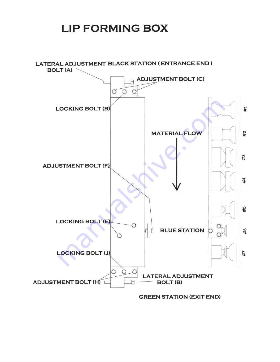
Page 21: ...d from the 2 station to the inside radius of the 1 outside box roller no double track The lateral setting is 2 500 from the inside wall of machine to the outside edge of the entrance of the forming box Entrance box mount Black station Vertical adjustment To raise this station loosen locking bolt B turn adjustment bolt C clockwise 1 4 turn two places tighten locking bolt B To lower this station loo...

Page 22: ... assembly Blue station The 6 station in the box is known as the swing shaft or the blue station The primary use of this station is to control the top lip of the gutter Adding pressure to this station will cause the top lip of the gutter to run into the facia and up hill on the face Relieving pressure from this station will cause the top lip of the gutter to run away from the facia and down Adding ...

Page 23: ... 21 ...

Page 24: ...wheel gap is 030 ADJUSTING TOP 8 STATION This station is color coded white on face side and red on back side To vertically adjust this station loosen locking bolt B two places turn adjustment bolt A counter clockwise to lower and clockwise to raise To adjust laterally loosen set screw C two places witch will allow roller to move laterally see pg 23 ADJUSTING BELL WHEEL To adjust bell wheel vertica...

Page 25: ... 23 ...

Page 26: ...nd spacers allowing clearance for the guillotine blade The guillotine is the most abused part of the machine To keep it in good working order lubricate all moving and pivoting parts weekly with a non detergent 90 WT oil and keep all nuts and bolt tight ADJUSTING GUILLOTINE POSITION The guillotine is moveable in all directions To move the guillotine up or down loosen bolt A 4 places loosen locking ...

Page 27: ...E The guillotine consists of a front and back plate and spacers allowing clearance for the guillotine blade The guillotine is the most abused part of the machine To keep it in good working order lubricate all moving parts and chains weekly with a non detergent 90 WT oil and keep all nuts and bolt tight ADJUSTING GUILLOTINE POSITION The guillotine is moveable in all directions To move the guillotin...

Page 28: ... 26 ...

Page 29: ... 27 ...

Page 30: ...d curve Visually you will be looking down lines 6 and 7 UP HILL This term describes a condition where the ends of the gutter are bowing up Visually you will be looking down lines 6 and 7 DOWN HILL This term describes a condition where the ends of the gutter are bowing down Visually you will be looking down lines 6 and 7 TOP LIP INTO THE HOUSE This term describes a condition where the ends of the t...

Page 31: ... 29 ...

Page 32: ...imately 3 in from edges Insert trimmed coil into the entrance guide system making sure coil is snug to both sides with free front to back movement push coil to the 1 drive station 4 The drum switch can be used for forward and reverse operation of the machine once machine is fed Run gutter to desired length and cut off using guillotine Run out support stands must be used to support gutter after 8 5...

Page 33: ...in from edges Insert trimmed coil into the entrance guide system making sure coil is snug to both sides with free front to back movement push coil to the 1 drive station 6 Activate jog button at entrance end using your right hand at the same time using your left hand to push the material so as to engage with the 1 drive rollers Jog the material approximately two feet RELEASE JOG BUTTON 7 Using jog...

Page 34: ...R THE GUTTER WILL RUN AWAY FROM ANY INTERFERENCE CAUSED BY THE SHEAR NOTE MACHINE WILL NOT PERFORM PROPERLY IF THERE IS INSUFFICIENT METAL IN THE FORMING BOX NOT ENOUGH LIP The most common problem with a ROLLFORMER is improper alignment of the metal in the machine This will cause several different problems with the finished product Make sure to keep entrance guides tight and in good working order ...

Page 35: ...LLERS 3 MEASURE AMOUNT OF COIL IN BOX 1 5 8 INCORRECT AMOUNT OF METAL 4 MEASURE RIGHT GUIDE SHOE NOTE MEASUREMENT MOVE RIGHT GUIDE SHOE FROM WALL TO THE LEFT 1 8 KEEP GUIDE PARALLEL TO WALL 5 MOVE LEFT GUIDE TO THE LEFT ALLOWING ENOUGH ROOM FOR COIL 6 INSERT A 2 LONG PIECE OF COIL STOCK INTO THE GUIDE SYSTEM UP TO THE RIGHT GUIDE 7 MOVE THE LEFT GUIDE TO RIGHT UNTIL IT LIGHTLY TOUCHES THE LEFT EDG...

Page 36: ...urn bolt F clockwise 1 2 turn Jog the gutter foreword 6 tighten bolt E 2 plcs see pg 21 Face of gutter where it meets bottom is running uphill but the top lip is straight Raise the exit end of the forming box GREEN station This is achieved by turning bolt J counter clockwise 1 2 turn Turn bolt H clockwise 1 2 turn or until tight 2 plcs see pg 21 Face of gutter where it meets bottom is running down...

Page 37: ...rs correct according to specifications above The only adjustment needed may be adding pressure to anti dent plate roller for away from the facia relieving pressure for into the facia The anti dent plate roller is located exit end just before shear To correct left curvature we must relieve pressure from the WHITE station Turn socket cap screws AW and CW counter clockwise 1 4 turn Turn socket cap sc...

Reviews: