background image

DDR OT/BACIP Gateway 

DDRA 015 v1.1 04/2010 

10 


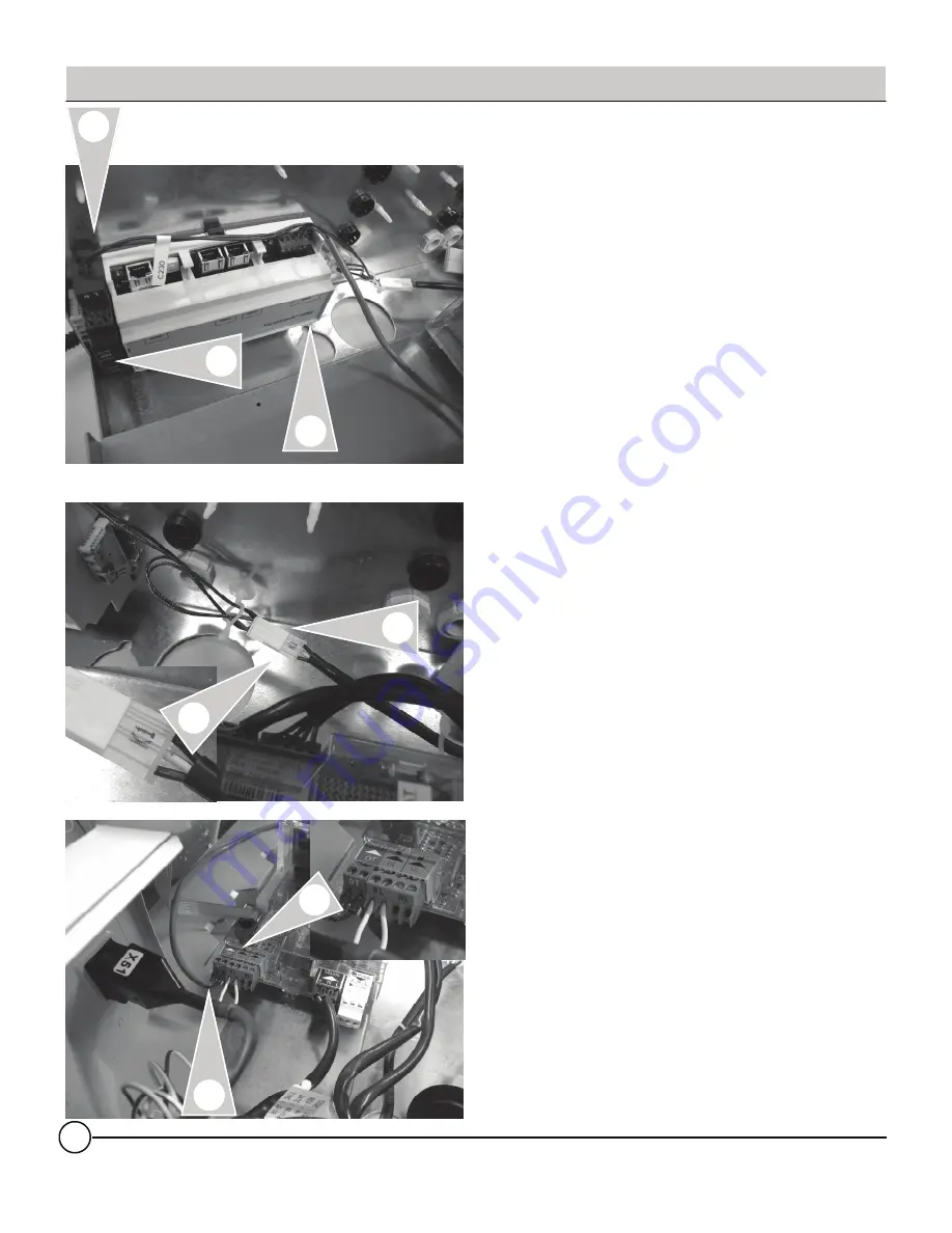
Installation Overview C230 ECO-A 

Information 

With the DIN rail mounted on the rear wall of the 
boiler control, follow the proceeding steps. 

1. Mount the gateway and power supply onto the 

mounted DIN rail by positioning the bottom DIN 
rail hooks at the bottom of the DIN rail. Tilt 

both units upwards and ensure upper clip hold 
devices to DIN rail.   

2. Locate the harness with the 230 label. Insert 

black wire into the L terminal of the power 

supply. Insert the blue wire into the N terminal 
of the power supply. Tighten both terminals of 

the power supply. 

3. Locate the K1 plug harness from within the 

control. Plug in the harness installed in the 
previous step to the K1 plug. 

4. Wire the OT communications harness into the 

green OT plug. Plug can be removed by 

unplugging from control. Insert wires and 
tighten terminal screws. Not polarity sensitive.  


Once all of the connections have been verified, the 
power switch of the control can now be turned on 

to perform the communication testing of the 
gateway. With the BMS plug-in connection to the 

gateway complete, it should be possible to start 
reading information from the boiler control.  

Summary of Contents for 704501

Page 1: ...plicable Controls DDR Boiler Controls for MCA Pro C230 ECO A and Gas 310 ECO Series Technical Installation and Configuration Information IMPORTANT Read and save these instructions for future reference Cautionary Statement The information presented in this document is only to be used by those familiar with its application and use DDRA 015 001 v1 1 04 2010 ...

Page 2: ...efer to another manual or other pages in this instruction manual Specific information Information must be kept in mind to maintain comfort Warning Before you operate this boiler read this manual carefully and take extra precautions to all safety and warning symbols or important items The operating manual is part of the documentation along with the boiler The installer is required to explain your h...

Page 3: ...ilar products There are no user serviceable parts on this control Power supply Install power supply in accordance with the regulation of the authorities having jurisdiction or in absence of such requirements in accordance with National Codes Please carefully read this manual prior to attempting installation Any warranty is null and void if these instructions are not followed The completeness and f...

Page 4: ...DDR OT BACIP Gateway DDRA 015 v1 1 04 2010 4 DDR OT BACIP Gateway505 This page is intentionally left blank ...

Page 5: ...n Section 2 Control Information Section 2 0 Information Page What s In The Box 6 Gateway Assembly Overview 7 Gateway Connection Overview 8 C230 ECO A Gateway Installation Steps 9 Gas 310 ECO Gateway Installation Steps 11 Gas 310 ECO OT Module Installation Steps 12 ...

Page 6: ...wing Qty Description 1 Communication Gateway on DIN rail 1 Gateway power supply on DIN rail 2 End stops on DIN rail 1 OT Interconnection cable 1 Gas C230 wiring harness 1 Gas C310 wiring harness 2 M5x8 Machine screws DIN Rail 2 M5 Lock nut DIN Rail 2 Power supply interconnection wires 1 DIN Rail Gateway and Power supply mounted 1 Installation manual ...

Page 7: ... 4 DIN rail locks 5 Power supply connection jumpers Warning When extending wire there is the possibility of exposure to electromagnetic interference Avoid running wires beside or near high voltage 120 240 VAC conductors If proximity to high voltage conductors cannot be avoided use stranded twisted pair of shield design wire Ensure that only one end of the shielding is grounded ...

Page 8: ...c to the application Information 1 2 1 BACnet IP RJ45 connection 2 OT connection terminals A and B 3 Power Connections to power supply Connection Overview Warning When extending wire there is the possibility of exposure to electromagnetic interference Avoid running wires beside or near high voltage 120 240 VAC conductors If proximity to high voltage conductors cannot be avoided use stranded twiste...

Page 9: ...he two stand offs removed enlarge the holes with 3 16 drill bit to allow for the M5 screws which fasten the DIN rail to the control housing WATCH FOR METAL SHAVINGS 3 With the holes enlarged insert the M5 screws through the DIN rail out towards the back of the control and tighten with supplied M5 lock nut Note Remove gateway and power supply from DIN rail Release the fastening tabs to allow DIN ra...

Page 10: ...supply Insert the blue wire into the N terminal of the power supply Tighten both terminals of the power supply 3 Locate the K1 plug harness from within the control Plug in the harness installed in the previous step to the K1 plug 4 Wire the OT communications harness into the green OT plug Plug can be removed by unplugging from control Insert wires and tighten terminal screws Not polarity sensitive...

Page 11: ...supply onto the mounted DIN rail by positioning the bottom DIN rail hooks at the bottom of the DIN rail Tilt both units upwards and ensure upper clip hold devices to DIN rail 3 Connect the OT cable connected to terminals A and B of the gateway to terminal block X29 terminals 11 and 12 Using a small flat blade screwdriver apply pressure into the terminal block and insert the wires Remove screwdrive...

Page 12: ...metal wall Bring plug towards the front of the control 2 Remove two screws from upper section of control One screw will be used to secure OT module to control 3 Position OT module on top of control with two wire harnesses towards the front of the control Secure module with screw from previous steps Locate the X16A male plug of the OT module and plug it into the X16 female socket from previous step...

Page 13: ... the X16 plugged into the OT module 2 Locate the K2 X24 and K2A X24A connectors on the boiler control Press the release tab on the K2 X24 connector and unplug from the socket 3 Locate the left harness connector X24A socket on the previously installed OT module and connect the K2 X24 plug into the X24A socket ...

Page 14: ...ler wiring harness and connect one of the multi plugs into the mating socket on the interface Note that the ribbon cable will have many plugs attached that can be connected to other accessory boards Use nearest plug without straining the cable against any other plug Once all of the connections have been verified the power switch of the control can now be turned on to perform the communication test...

Page 15: ... 04 2010 Configuration of Gateway Overview Configuration Information Section 3 0 Information Page Configuring BACnet IP Settings 16 BACnet Device Settings 17 BACnet Objects 18 Variables 19 LED Troubleshooting 20 Technical Information 21 ...

Page 16: ... computer s IP address to 192 168 88 90 subnet mask 255 255 255 0 Restart the Gateway by cycling the power off and then on again Open a browser window and insert the following URL http 192 168 88 89 admin The default user name password is admin and admin without the quotes This can be renamed in the Change Password screen At this point you will see the Configuration pages IMPORTANT Make sure that ...

Page 17: ...specified a duplicate IP Address Any Computer on the network should now be able to access these configuration screens BACnet Device Settings You can now reconfigure these settings according to your network requirements Make sure that you press SAVE on every screen where you make changes The new setting will not take effect until the Activate Configuration screen has been confirmed These configurat...

Page 18: ...nalog Input 6 Room Set point temperature C F T Analog Input 7 Outside Temperature C F T Analog Input 8 Return Water Temperature C F B Analog Input 9 Flue Gas Temperature C F B Analog Input 10 Boiler Heat Exchanger Temperature C F B Analog Input 11 Boiler Fan Speed Hertz B Analog Input 12 Water Pressure Bar PSI B Analog Input 13 OEM Fault Code 0 255 B Analog Input 14 OEM Diagnostic Code 0 65535 B B...

Page 19: ...ature R C F Boiler Heat Exchanger Temperature R C F Boiler Fan Speed R Hertz Water Pressure R Bar PSI Boiler Fault no fault fault R 0 1 Flame Status no flame flame R 0 1 Service Required not req d req d R 0 1 Lockout Reset R 0 1 Low Water Pressure R 0 1 Gas Flame Fault R 0 1 Air Pressure Fault R 0 1 Water Over Temperature R 0 1 Units Metric Imperial C F Bar PSI W 0 1 Set point Either Boiler Temp o...

Page 20: ...DDR OT BACIP Gateway DDRA 015 v1 1 04 2010 20 Technical Information Trouble Shooting Problem LED2 is flashing Control BMS Mode LED 1 flash per second OK LED 4 flash per second No Communication ...

Page 21: ...5 4 3 1 24VAC Power Supply Connections 3 BACnet RJ45 BMS Connection 4 N A 5 N A 6 N A 7 N A 8 OT Status LED 2 Power LED indicator 9 OT connection to boiler control A and B PCB Identifiers Specifications 2 9 Caution Static sensitive components may be damaged by improper handling or work within the control Ensure all possible measures are taken to eliminate build up of static electricity ...

Page 22: ...DDR OT BACIP Gateway DDRA 015 v1 1 04 2010 22 KWE Technologies Group 750 McMurray Road Waterloo Ontario Canada N2V 2G5 Tel 519 747 5042 Fax 519 747 4448 www kwe tech com info kwe tech com ...

Reviews: