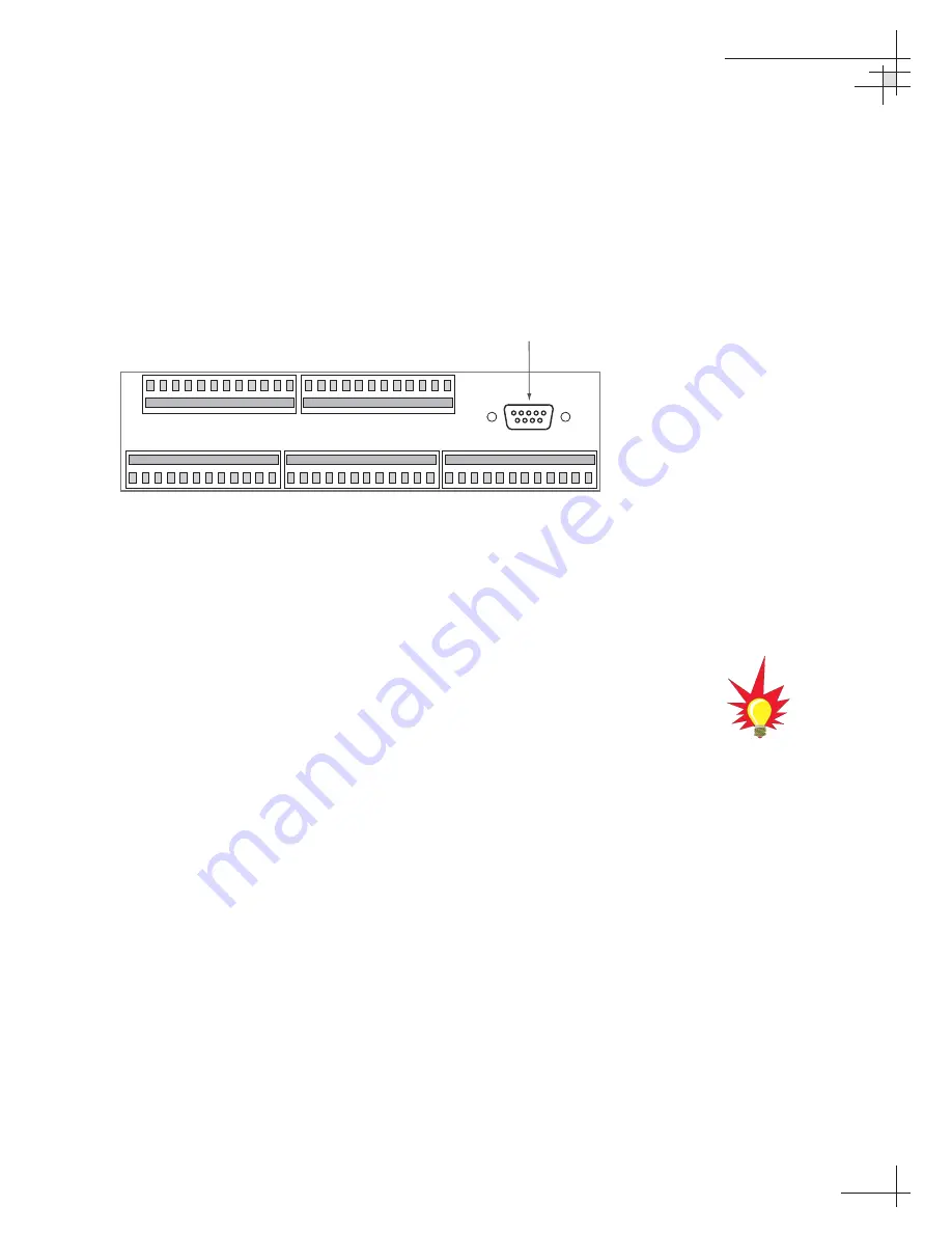
The diagnostics procedure requires Windows Hyperterminal (or
other terminal emulation software, such as PROCOMM). Use the
settings appropriate to your application.
1. Connect one end of the PC data cable to
the DB9 maintenance port connector on the rear of
the ADCU. Connect the other end to the serial port
on your PC (a 9-pin/25-pin connector adapter may
be needed for some PCs).
2. Open the terminal emulation software and
establish the following settings:
• 9600 baud
• no parity
• 8 data bits
• 1 start bit
• 1 stop bit
• no flow control
3. Apply power to the TracVision G4 system and
allow the system to complete full initialization.
Data should be scrolling on the PC display to
identify any system problems detected. If no data
is seen, recheck your connections and the terminal
software setup.
4.7
Maintenance Port Parser
Commands
TracVision G4 system parser commands are detailed in
Appendix H on page 151.
Troubleshooting
54-0147
99
1
2
11
10
9
8
7
6
12
5
4
3
13 14
23
22
21
20
19
18
24
17
16
15
25 26
35
34
33
32
31
30
36
29
28
27
48 47
38
39
40
41
42
43
37
44
45
46
60 59
50
51
52
53
54
55
49
56
57
58
Maintenance
Port (DB9)
Figure 4-2
ADCU Maintenance Port
Appendix F on page 143
shows the
diagnostic information available in
the startup data sequence.
Summary of Contents for TracVision G4
Page 127: ......


