10
54-0215 Rev. C
2.3
Preliminary Testing
Before connecting and mounting the gyro to your system, a simple familiarization test is
suggested if this is your first introduction to the product. This test will also verify proper
unit operation and assist in troubleshooting.
Equipment needed to test the gyro:
•
+5 VDC power supply
•
Computer with an RS-232 input and a terminal emulation program
(such as Windows Hyperterminal)
•
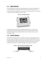
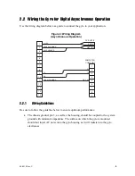
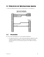
Interface cable with a female 15-pin single-row Dualobe connector on
one end and a DB9 connector on the other end, wired as shown in
Figure 4 on page 9
2.3.1 Test
Procedure
Follow the steps below to test the gyro for proper operation.
1.
Place the DSP-3000 module on a flat surface with the mounting surface down.
2.
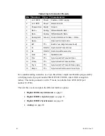
Connect the +5 VDC (±10%) power supply positive to pin 1; connect the negative
to pins 2 and 3.
3.
Connect the DB9 plug from the test cable harness to the computer’s COM port.
Select the serial port (to which the cable was connected), open the test data
acquisition program, and select the following communications program settings:
•
38,400 baud
•
8 data bits
•
1 stop bit
•
no parity
•
no flow control
4.
With the gyro held stationary, the indicated mean (30-second average) input rate
should be less than 0.005°/s, excluding Earth rate. If no data is received, check the
wiring for proper data line connection.
To calculate the Earth rate for your geographical area, use the following
formula:
Earth rate = -15.04107 x sin(latitude)
Note: Northern latitudes are positive and southern latitudes are negative.


