54-0215 Rev. C
5
1.2.1
Output Orientation
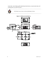
The DSP-3000 senses rotation on an axis perpendicular to the plane of the baseplate. An
arrow on the product’s serial number label (located on the side of the unit) shows the
rotational direction corresponding to a positive output. Looking at the gyro from overhead,
a clockwise rotation will produce a positive output.
Figure 2: Clockwise Rotation
To minimize output errors and cross-coupling to the sensitive axis of the gyro, the
mounting surface should be parallel to the plane normal to the rotational axis. If this
alignment is not observed, the output data will vary as a function of the cosine of the
misalignment angle.
1.2.2 Interface
Connector
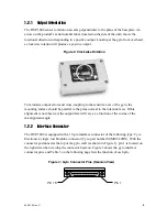
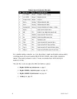
The DSP-3000 is equipped with a 15-pin interface connector of the following type: Tyco
Electronics’ single-row Dualobe connector (Tyco part number SSM015L2HN). With the
connector positioned at the top of the gyro wall (as shown in Figure 1), pin 1 is located on
the right side when viewing the connector head-on. Figure 3 shows the gyro interface
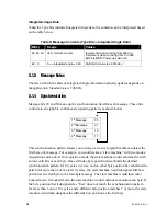
connector pins, and Table 3 on the following page lists the function of each pin.
Figure 3: Gyro Connector Pins (Head-on View)
Pin 1
Pin 15


