___________________________________________________________________________________________
8
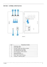
EA200A
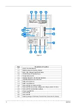
TB2
A1
A2
C1
C2
S1
S2
VR1
VR2
B+
B-
TB3
TB1
F+
F-
AC2
AC1
Figure 5
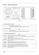
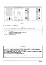
4.4 TB3 Signal Input / Output Terminal
TB3
A1
、
A2
Parallel Controller Analog Voltage Input (0 to 10Vdc or +/-5Vdc) A1 is GND
C1
、
C2
CT Input (N:5A 5VA)
S1
、
S2
Sensing Input
VR1
、
VR2
External Voltage adjust potentiometer
(1KΩ 1/2W)
Must be shorted when not in used.
B+
、
B-
DC24V Power input
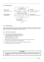
ATTENTION
※
This Automatic Voltage Regulator is not equipped with loss-Sensing Protection / Over Excitation
Protection. An additional Over-Voltage Protection device for load may be required to avoid possible
damage to the equipment or severe personal injury or death.
※
The connection wire for VR1, VR2 and A1, A2 must be shielded wire, the grounding wire of shielded
wire should be as close as possible to the AVR.
※
The A1 and A2 signal must be isolated from the power.
※
All the power of EA200A protection system were supplied by 24Vdc, the B+ and B- terminal must be
connected correctly, otherwise all the protection, Self-Excited, and the Field Current meter cannot be
used.

