


User Manual
KEA 320 / KEA 320 RP
BA-KEA 320 / KEA 320 RP_EN Version 03
Date: 16.Sep.2020
Page 10 of 21
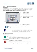
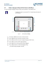
Status symbols
Menu screen
Symbol
Caption
Description
Main Screen
Voltage Display Mode
The index of the symbol indicates whether delta or wye voltage is
displayed and which phases are displayed.
Single Line Dia‐ gram
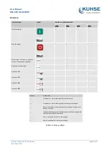
Rotating Field CW
Generator, mains or busbar rotating field moves clockwise.
Rotating Field CCW
Generator, mains or busbar rotating field moves counter-clock‐
wise.
Power Detected
Power is detected at the respective measuring point (generator, busbar
or mains).
Monitoring Enabled
Indicates that the engine delayed monitoring has expired and the
monitoring functions are enabled.
Power Imported
Power is imported (at mains interchange).
Power Exported
Power is exported (at mains interchange).
Alarm List
Alarm Condition Present
Indicates that corresponding alarm condition is still present.
Alarm class A/B/C/D/E/F present
Symbol with "!" indicates that an alarm of class A/B/C/D/E/F is present.
Alarm class A/B/C/D/E/F not
present
Symbol without "!" indicates that an alarm of class A/B/C/D/E/F is not
present.
Setpoints
Generator Power
Indicates the generator power (actual value).
Mains Power
Indicates the mains power (actual value).
Synchroscope
Phase Angle
Indicates the actual phase angle between busbar and mains or busbar
and generator.
Sequencing
Breaker Closed
GCB of respective genset in sequence is closed.
Breaker Open
GCB of respective genset in sequence is open.
Add-on
Generator is becoming "Add-on" to the (multiple) genset system.
Add-off
Generator is going "Add-off" from the (multiple) genset system.
LogicsManager
Delay ON
Delay before output becomes TRUE.
Delay OFF
Delay before output becomes FALSE.
TRUE/enabled
Variable is TRUE (LogicsManager). The bit
is enabled (CAN Interface).
Relay activated (Discrete Outputs)
FALSE/disabled
Variable is FALSE (LogicsManager). The bit
is disabled (CAN Interface).
Relay deactivated (Discrete Outputs)


