


User Manual
KEA 320 / KEA 320 RP
BA-KEA 320 / KEA 320 RP_EN Version 03
Date: 16.Sep.2020
Page 6 of 21
2.2
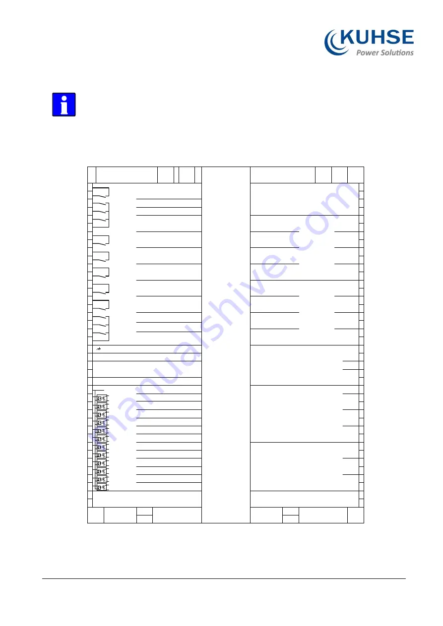
Wiring Diagram
The Protective Earth terminal 61 is not connected on the sheet metal
housing.
-
Use the protective earth (PE) connector located at the bottom center of
the sheet metal housing instead.
Fig. 6:
Wiring diagram KEA 320 RP/KEA 320 (-LT)
8
0
7
8
7
9
7
7
7
6
7
5
7
4
7
3
7
2
7
1
7
0
6
9
6
8
6
7
6
6
6
5
6
3
6
4
6
2
6
1
6
0
5
9
5
8
5
7
5
6
5
5
5
4
5
3
5
2
5
1
5
0
4
8
4
9
4
7
4
6
4
5
4
4
4
3
4
2
4
1
1
3
2
4
5
6
7
8
9
1
0
1
1
1
2
1
3
1
4
1
5
1
6
1
8
1
7
1
9
2
0
2
2
2
4
2
6
2
8
3
0
3
2
3
4
3
6
3
8
4
0
Te
rm
in
al
s
K
EA
3
2
0
USB
Host
In preparation
USB
Device
Sc
re
w
te
rm
in
al
s
Ethernet
#A
CAN#3
CAN#1
Sc
re
w
te
rm
in
al
s
1:CAN_GND
2:CAN_L
3:CAN_SHIELD
4:CAN_H
+
-
MPU/Pickup
[D12]
[D11]
[D10]
[D09]
[D08]
[D06]
[D07]
[D05]
[D04]
[D03]
[D02]
[D01]
[R12]
[R11]
[R10]
[R09]
[R08]
[R07]
[R06]
[R05]
[R04]
[R03]
[R02]
[R01]
+
-
Emergency Stop
*1
Start in Auto
*1
Low oil pressure
*1
Coolant temperatur
*1
Sprinkler
*1
Reserve
*1
Reply: MCB open
Reply: GCB open
Block start
*1
Fuel low level
*1
Reserve
*1
Start without load
*1
Common terminals (67-78)
Horn
*1
Genset available
*1
Signal „engine running“
*1
Command MCB off
*1
Command MCB on
*1
Command GCB off
*1
Command GCB on
*1
Freely configurable
*1
Operating solenoid
*1
Starter motor
*1
Auxiliary drives on
*1
Ready for operation
Earth
NC
Power supply isolated
8-40VDC
*2
Auxiliary excitation D+ isolated
Busbar voltage (system1) L2/N
480 VAC
480 VAC
480 VAC
480 VAC
480 VAC
480 VAC
480 VAC
480 VAC
480 VAC
480 VAC
Busbar voltage (system1) L1
Generator voltage N
Generator voltage L3
Generator voltage L2
Generator voltage L1
Mains voltage N
Mains voltage L3
Mains voltage L2
Mains voltage L1
Analog output [AO 02]
(+/-10VDC / +/-20mA /PWM)
Voltage Biasing
Do not
connect!
-
+
-
+
Engine
GND
+
-
+
-
+
-
s1
s2
s1
s2
s1
s2
s1
s2
L1
L2
L1
L3
Mains or Ground current
(isolated) 1A/5A compatible
Generator current (isolated)
1A/5A compatible
Analog input Typ1
(0 - 2000 Ohm /
0/4 - 20mA /
0 - 1V)
Analog output [AO 01]
(+/-10VDC / +/-20mA /
PWM) Speed Biasing
[AI 01]
[AI 02]
[AI 03]
1:CAN_GND
2:CAN_L
3:CAN_SHIELD
4:CAN_H
RS485#1
CAN#2
1:RS485_A
2:RS485_B
3:RS485_GND
4:RS485_SHIELD
5:RS485_Y
6:RS485_Z
Sc
re
w
te
rm
in
al
s
[AO 01]
[AO 02]
*1
configurable via LogicsManager
*2 V
nom
=12/24V SELV


