background image


Kudo3D Bean User Manual 

Ver. 1.0 

8 of 14 

VI. Linear Guide Calibration 
 

If the carrier of the linear guide is loose, you would need to calibrate it to improve the surface quality.   

Under this situation, you can swing the platform arm horizontally. Please follow the steps below and also 
refer to the video 

https://youtu.be/bQXxF9VVSp8

.     

1.  Remove the platform 

2.  Remove the arm/carrier assembly by rotating the linear screw manually so the assembly comes out from 

the top of the linear screw.   

3.  Remove the anti-wobbling piece with the brass nut inside the arm by loosening the pivoting nut.   

4.  Loosen those two tiny set screws on the cylinder in the carrier and rotate the center cylinder piece with 

those two screws. Rotate the cylinder to a position that the carrier is tight but not too tight. The carrier 
must be tight enough so there is no horizontal swinging of the platform arm.    The carrier cannot be too 
tight so weight of the platform can pull the platform down.    Tighten the set screws. This is a try-an-error 
process. We spent quite a lot of time to calibrate the carrier.   

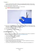
5.  Put only the arm back in the linear guide, it may or may not slide down. But when you lock the platform 

on the arm, it has to move down freely by the gravity. There should be no horizontal movement at all.   

6.  If carrier is too tight or too loose, repeat step 4 and 5 until you find the proper tightness.   

7.  Put the anti-wobbling piece back. Adjust the nut so that the anti-wobbling piece can move freely and the 

gap between the anti-wobbling piece and the holding arm is minimum. This is also very important to 
minimize the horizontal movement of the arm. If the nut is too tight, the anti-wobbling piece is locked. If 
the nut is too loose, there is a big gap between the anti-wobbling piece and the arm and may cause z 
zero problem.   

8.


Put the arm/carrier assembly back by rotating the linear screw below manually. You would need to align 
the brass nut to the linear screw and press the arm downward with one hand while rotating the linear 
screw with another hand.


VII. Teflon Film Replacement 

Your printer comes with 12 screws and 12 tubes to help you replace the film. Please refer to the video for 
the steps. 

https://youtu.be/9OxvdgD-b0A


1.  Place the Teflon film between the container and the securing ring


2.  Insert 12 studs


3.  Insert the 12 screws M3 x 8 and screw down one to two rotations


4.  Press the securing ring into the trench


5.  Follow the video and replace 12 tubes with 12 M3 x 6 screws. Make sure they pass through the holes of 

the film and screw down only one to two rotation.    You need to do two screws in the opposite position 
at a time to maintain the balance.    Do not run it randomly. 


6. 

Replace the 12 M3 x 8 screws with 12 M3 x 6 screws.       

To save time, you need only 12 screws to secure the film.      We leave a big design safety margin 
because we can’t increase the number of screws after injection mold is made.     

We are still investigating the impact of the film tightness on the print and vat sealing.    If there is not 
much difference, we will stretch the film less to simplify the film replacement process later. 


Summary of Contents for Bean

Page 1: ... by Kudo3D This material may be distributed only subject to the terms and conditions set forth in the Creative Commons Attribution NonCommercial NoDerivatives 4 0 International License or later The latest version is presently available at http creativecommons org licenses by nc nd 4 0 ...

Page 2: ... of Contents I Product Introduction 3 II Standard Package Materials and Tools 5 III Setting up the printer 5 IV Printing Flow 5 V Z zero Calibration 7 VI Linear Guide Calibration 8 VII Teflon Film Replacement 8 VIII Software Tool Chain 9 IX FAQ 12 ...

Page 3: ...otion Voltage 20 x 20 x 40 cm 6 8 x 12 x 16 cm 47 μm 10 μm 10 20 mm hr 15 lb 6 5Kg 60W 405nm LED 2K LCD panel 95 for feature sizes 1 5mm PSP D Drum type PSP container Web based Via Wi Fi repeater or router 3rd party compatible Pre calibrated zero with an optical sensor Windows Mac Linux or any portable devices Patent pending anti wobbling mechanism AWM 100 240 V 1 Cover 2 Build Platform 3 Resin Co...

Page 4: ...ng the gap When moving the linear stage down the platform must be attached The carrier is tightened to prevent horizontal swinging so it needs the weight of the platform to move down smoothly Must use dry lubricant to lubricate the linear screw and guide CE FCC Notice For EN 55022 2010 warning This is a class A product In a domestic environment this product may cause radio interference in which ca...

Page 5: ...IP address is assigned to the printer by your router automatically Once you press the Print button you can remove these devices without interrupting the printing Inspect and make sure the LCD surface and the lower surface of the Teflon film are clean and there are no dusts between these two surfaces IV Printing Flow 1 Design or download a digital model 2 If the model is not in the stl format pleas...

Page 6: ...in excel Upload it to the printer 18 Make sure the Begin layer no starts from 1 and the Slice Thickness is correct 19 Press the Print button 20 For big models that do not have proven parameters we suggest monitoring the printing process for the first 10mm until you are sure that model does not drop You can Pause the printing process and press the Check button to lift the platform up to confirm If ...

Page 7: ...k the oxygen to accelerate the post curing 27 Use a cutter to remove the supports 28 You may need to polish the surface with supports V Z zero Calibration Normally you do not need to calibrate Z zero You need to calibrate the z zero only when a new platform is used for the first time Please refer to the video https youtu be NPw4VYMV7M 1 Loosen the four screws on the side of the platform 2 Lift the...

Page 8: ...obbling piece can move freely and the gap between the anti wobbling piece and the holding arm is minimum This is also very important to minimize the horizontal movement of the arm If the nut is too tight the anti wobbling piece is locked If the nut is too loose there is a big gap between the anti wobbling piece and the arm and may cause z zero problem 8 Put the arm carrier assembly back by rotatin...

Page 9: ...may be able to repair the model with the Automatic repair of Netfabb basic If Netfabb basic fails to repair you can upload your model to Netfabb online https service netfabb com to repair If Netfabb online also fails to repair please try windows 3D builder 3 Hollowing Meshmixer If you have multiple shells in a model you may experience difficulty in hollowing In this case you need to use Netfabb on...

Page 10: ...tain area to print You can chanage the hollowing parameters and press Update Hollow To aoid a huge vacuum force during printing the model MUST have vent holes After pressing Generate Holes you can move the red dots to where you want the holes to be opened It is better to open holes at the bottom or at a spot that is hard to see The hole radius must be greater than 2mm Once the hollowing and hole g...

Page 11: ...e following circumstances All downward facing tips or hills on the model Overhanging region distance between two supports depends on the overhanging slope Internal supports to counteract the non uniform shrinkage caused by the structure such as a box with no lid To counteract the non uniformity of intensity and higher separation force close to the anchoring side of the vat thicker or denser suppor...

Page 12: ...ved in the Raspberry Pi 3 memory You can delete them with Remove button or download them with Download button Before printing you need to press Load button to load them After loading the model file and printing configuration file name should appear in the State pane When you press the Advanced button you can modify the numbers under Advanced Settings You can define layer zones and define numbers f...

Page 13: ...25 to 0 3mm thickness Please refer to the software manual to set the right thickness for the base 4 2 The build platform is not well zeroed or leveled and leave a gap between the plate and the vat floor The gap will form a thick attachment layer after exposures The exposure time may not be enough for such a thick layer and thus the adhesion between the base and the build plate is weak Even if the ...

Page 14: ...on cup formed by shrinkage Vacuum forces are often catastrophic 7 Why the Machine State is not operational When the raspberry pi fails to communicate with the mega2560 the machine state will show connecting This could happen due to the following reasons 7 1 The firmware of mega2560 is corrupted 7 2 The USB cable or connectors between the mega2560 and Raspberry Pi has a problem 7 3 The mega2560 is ...

Reviews: