RA2584
Operator‘s manual
Original operator‘s manual
Edition
10.2012
Date of print
09.2014
Language
EN-
EU
Machine number
VF65882401 –
Model
VF6588
Document number
VF16661959.EN-EU
Page 1: ...RA2584 Operator s manual Original operator s manual Edition 10 2012 Date of print 09 2014 Language EN EU Machine number VF65882401 Model VF6588 Document number VF16661959 EN EU ...
Page 2: ...rer Kverneland Group Kerteminde AS Taarupstrandvej 25 DK 5300 Kerteminde Denmark Tel 45 65 19 19 00 7 60 m 8 40 m 1950 kg VF6588 _ _ _ _ Copyright by Kverneland Group Gottmadingen N V Germany Reproduction transfer to other media translation or the use of extracts or parts of this manual without the explicit permission of Kverneland is not permitted All rights reserved The contents of this operatin...
Page 3: ...r pitch 45 Lifting the tines 47 Working depth 48 Road transport 50 Safety 50 General 51 Prior to road transport 52 Road transport 57 Preparations on the field 58 Safety 58 General 59 Folding the machine into the work position 60 Basic settings 63 Operation 66 Safety 66 General 67 Swathing 68 Swath deposit 69 Adjusting the swath width 73 Driving on headlands 73 Cleaning and care 74 Safety 74 Cleani...
Page 4: ...ly with warranty conditions have a fully functional machine in good working order at all times Training Your dealer will provide instruction on operation and care of the machine Information for the employer All personnel are to be regularly but at least once a year instructed on the use of the machine in accordance with the regulations of the national organisation for Health and Safety at Work Unt...
Page 5: ...ion The Examples pictogram indicates examples that assist under standing of the instructions The spanner indicates tips for assembly or adjustment work This arrow in the diagram shows the direction of travel The brush indicates the points that must be lubricated using the brush The grease gun indicates the points that must be lubricated using the grease gun Switch on the tractor Secure the tractor...
Page 6: ... in the interest of your own safety in the interest of the safety of others to ensure the safety of the machine Numerous risks can result from handling agricultural machinery in the wrong way Therefore always work with particular care and never under time pressure The employer should Inform all persons who work with the machine about this safety information at regular intervals and in accordance w...
Page 7: ... related labels attached to the machine indicate potential hazards The labels must not be removed Illegible or missing labels should be replaced You can obtain new labels as spare parts from your dealer Warning signs on the machine ...
Page 8: ...stance from the rotor when it is rotating Nobody may remain in close proximity to the machine when rakes and swathers are running Otherwise serious or fatal injury may be caused as a result Distance from tractor When the machine is being coupled uncoupled or operated there should be no one between the tractor and the machine Otherwise serious or fatal injury may be caused as a result Risk of crush...
Page 9: ...t Secure the machine with wheel chocks Always secure the machine with wheel chocks to ensure it cannot roll away when it is in park or stop position Otherwise serious or fatal injury may be caused as a result PTO shaft speed 540 rpm The specified maximum PTO shaft speed of 540 rpm must not be exceeded Otherwise damage to the machine may be caused as a result Do not exceed the maximum hydraulic pre...
Page 10: ...an employee from a dealership or the manufacturer or by a factory representative Operation without proper training can lead to damage to the machine due to incorrect operation or may cause accidents Safety is your responsibility Follow the safety regulations Ensure that all operators comply with the safety instructions Prevent serious or fatal accidents by following the safety instructions Instruc...
Page 11: ...and even life threatening injuries No reversing while the drive is running Never drive in reverse with the PTO shaft drive switched on and in the work position if people could enter the working area of the machine Switch off the PTO shaft drive Rotating unprotected parts can damage the machine and cause life threatening injuries Specified workwear Do not wear loose fitting clothing Loose fitting i...
Page 12: ...on The rotating PTO shaft is protected by the PTO shaft guard Ensure that the guard is not damaged Fasten the PTO shaft guard in position by connecting the chains on the implement and the tractor Unguarded PTO shafts can cause life threatening injuries Make sure the machine is standing level Before changing from the transport to the work position and vice versa make sure the machine is standing le...
Page 13: ...y damage the machine Unrestricted field of vision to the rear After it has been coupled ensure that you have an unrestricted view of the machine in both its work and transport positions At the very least use the panorama mirror provided by the tractor manufacturer Otherwise hazardous situations may not be detected in time and accidents or damage may be caused as a result Check the angle of lock On...
Page 14: ... Otherwise short circuits may occur and the electronic system may be damaged Observe the operating manual of the PTO shaft manufacturer Observe the operating manual of the PTO shaft manufacturer It will provide you with instructions on how to handle the PTO shaft correctly If these instructions are ignored damage may be caused to the PTO shaft and machine Risk of tipping due to unsecured quick rel...
Page 15: ...t High pressures in the hydraulic system The hydraulic system is under high pressure Regularly check all lines hoses and screwed connections for leaks and externally visible damage Only use suitable tools when looking for leaks Rectify any damage immediately Oil escaping under pressure may result in injuries and fires Seek medical attention immediately if injuries occur Replace hydraulic hoses eve...
Page 16: ...e empty weight of the tractor must be greater than the weight of the machine The driver and keeper of the vehicle are liable should these conditions not be observed Close the ball valve Close the ball valve before driving on the road If the ball valve is open andthereisanoperatingerror themachinemaydroporswingoutunex pectedly This could causetraffic accidents and accidents with fatal con sequences...
Page 17: ...sult Check hitch pins Hitch pins must be in perfect condition Hitch pins must show no signs of wear and be properly secured Otherwise hitched machines may detach themselves of their own accord Accidents with serious or fatal injuries may be caused as a result Check release cords on quick release couplings Release cords must hang loose and must not allow a release in their lowered position Hitched ...
Page 18: ...ing operation Make sure that you have an adequate view Only begin work when the immediate vicinity is cleared of any persons or objects Serious or fatal injury may be caused as a result Retighten all nuts bolts and screws Regularly check that bolts and nuts are correctly tightened Retighten bolts if necessary Nuts and bolts can work loose when the machine is used Otherwise the machine may be damag...
Page 19: ...nd the machine during manoeu vring Secure the tractor against rolling away turn off the engine and remove the ignition key Secure the machine against rolling away use wheel chocks Ensure that the sustainer is securely locked Place the PTO shaft in the holder provided Do not uncouple the hydraulic hoses until the hydraulic system is at zero pressure Failure to observe these instructions can result ...
Page 20: ... Switch off the PTO shaft drive Depressurise the hydraulic system Whenever possible uncouple the tractor Switch off the tractor and remove the ignition key Ensure the machine is standing on firm secure and level ground and provide additional support if necessary Secure the machine against rolling away use wheel chocks Only if these regulations are observed can safe working be ensured during care a...
Page 21: ... pin and screw connections Further regulations Observe the regulations In addition to the safety information given above please observe the following Accident prevention regulations Generally recognised safety regulations occupational health requirements and road traffic regulations The instructions provided in this operating manual Regulations relating to operation maintenance and repair Warranty...
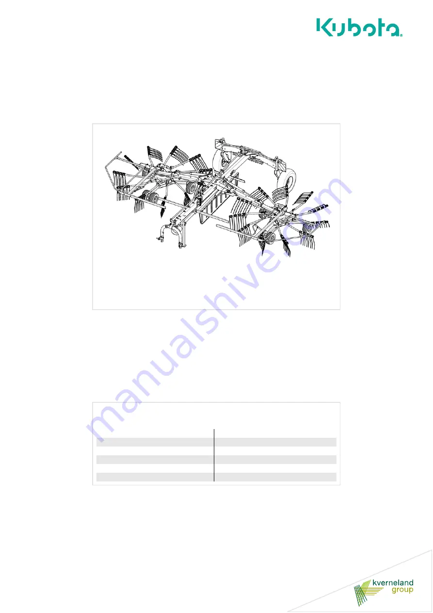
Page 22: ...res meets all the requirements of modern crop harvesting engi neering All the important functions for field use are controlled during operation The following functions can be set Deposit of crop in single rotor operation via the hydraulic single lift Individual working depth of both rotors Swath width The rake can be pulled by tractors of 40 kW 56 hp or more Extensive equipment The machine is equi...
Page 23: ...eflector bar Main frame Attachment carrier Deflector bar Drive Tine support Tines Swath former Rotor gear Transport chassis Rotor chassis Transport holder for tine supports Sustainer Steering Tine arm shaft Telescopic arm Lifting arm Tine cover stowage area ...
Page 24: ...rt position 3 44 WR Width without the upper tine supports for transport position when using tyres 11 5 80 15 3 and 380 55 17 2 89 and 2 98 WT Maximum width with mounted tine supports 2 98 T Track width 2 61 M Distance between lights 2 30 N Height of lights 1 29 R Height of bottom reflectors 0 35 S Distance between bottom reflectors 2 08 Machine attachment carrier cat 2 lowered to 20 cm from the gr...
Page 25: ...Getting to know the machine 25 Dimensions Work position m LT Length 6 24 HW Height in work position 1 50 WW Working width 7 60 8 40 WO Raking width 8 50 X Distance between the rotors 0 30 1 15 ...
Page 26: ...xle load 1195 based on load supported on lower link Output connections Minimum output of the tractor 40 kW 56 hp Lighting power supply 12 V 7 pin plug socket ISO 1724 Hydraulic connections 1 x double acting hydraulic control unit 1 x single acting hydraulic control unit Hydraulic pressure 150 210 bar Maximum PTO shaft speed 540 rpm Lower link Fixable in height and laterally ...
Page 27: ...chine 80 dB A Swath deposit Swath former with auto swivel Standard Rotors tine supports tines Number of rotors 2 Number of tine supports per rotor 12 swaths on the left 12 swaths on the right Number of tines per tine support 4 Removable tine arms Standard Rotor height adjustment Mechanical Hydraulic single lift Tine saver Wheels Rotor chassis 16 x 6 50 8 6 PR Tandem axles on rotor chassis Transpor...
Page 28: ...With the switch select the function A B or C and then execute the function with the single acting hydraulic control unit Protect electrical parts against moisture The electronic control system pilotbox and electrical plug con nections must be protected against damp and penetrating mois ture Dampness in electronic devices can lead to leakage current which results in malfunction On Off switch Contro...
Page 29: ...ully with the single acting hydraulic control device on the tractor Single acting hydraulic control unit on the tractor Headlands Using the tractor s single acting hydraulic control unit raise both rotors to the headland position then lower them Single acting hydraulic control unit on the tractor Mechanical locking mechanism cable Lowering the left rotor Remove the right side shaft Raise the machi...
Page 30: ...d then lower it Double acting hydraulic control unit on the tractor Single acting hydraulic control unit on the tractor Swath width Raise the machine into the headland position using the tractor s single acting hydraulic control unit Adjust the swath width using the double acting hydraulic control device on the tractor Lower the machine to the work position using the tractor s single acting hydrau...
Page 31: ...ired to assemble the machine Do not perform assembly work yourself The following points are required to be met for the machine to be in proper condition Observance of a sequence of work steps Compliance with tolerances and torques Knowledge of work safety during assembly Incorrect assembly can result in damage to the machine or accidents Checklist for parts which were supplied loose Quantity PTO s...
Page 32: ...ower link Set the tractor and machine to the smallest angle of lock Secure the tractor against rolling away shut off the engine and remove the ignition key Switch off the tractor and secure it Before you dismount Switch off the tractor Remove the ignition key Secure the tractor against rolling away An unsecured tractor can run you over or trap you Serious or fatal injury may be caused as a result ...
Page 33: ...the block minimum clearance a 20 mm Shorten both the sliding tube and guard tube to the same size Deburr the ends of the tubes Remove the swarf Grease the sliding surfaces well Fitting the PTO shaft Make sure that you fit the PTO shaft in the correct installation position There is a mark on the guard tube of the PTO shaft Check the length of the PTO shaft and shorten it if necessary Fit the PTO sh...
Page 34: ...chine swerves to the side or if the wheels do not run parallel the track and steering must be readjusted at an authorised workshop Check if the target measurements are correct If discrepancies are found consult your dealer See chapter Checking the track page 90 Track arm Steering arm Track rod Steering rod Never carry out work on the steering Contact your dealer if specifications differ Never carr...
Page 35: ...ections Hydraulic connections Observe the safety information Observe the safety information Disregard for safety information can lead to serious or fatal injury See chapter Safety page 6 Increased risk of injury When the machine is being coupled to the tractor there is an increased risk of injury Therefore Never stand between the tractor and machine Secure the tractor against rolling away Slowly a...
Page 36: ...al of the tractor manufacturer lift slightly and secure Slightly raise the lower link Secure the tractor against rolling away shut off the engine and remove the ignition key Swivel in the sustainer See Swivelling in the parking stand page 37 With the lower link in the work position lift it off the ground until the main frame of the machine is tilted approximately 1 degree forwards Engage the lower...
Page 37: ...ling the machine to the tractor raise and secure the sustainer Switch off the tractor and secure it shut off the engine and remove the ignition key Pull out the pins in the sustainer Swivel in the sustainer Undo the pins on the sustainer and engage them Pin Sustainer ...
Page 38: ...ing the length of the PTO shaft page 32 Check that the tractor s PTO stub shaft is clean and lubricated Couple the PTO shaft to the tractor and the machine Ensure that the PTO shaft is engaged on the shaft ends Secure the guard tubes so that they cannot rotate at the same time Couple the wide angle joint to the machine s PTO stub shaft PTO shaft Chain Wide angle joint Tractor Wide angle joint with...
Page 39: ...provided on the left and right behind the warning plates on the transport chassis and engage them securely Wheel chock Secure the tractor against rolling away Never remove the wheel chocks if the tractor is not otherwise secured against rolling away Persons could be run over by the machine or the tractor Serious or fatal injury may be caused as a result ...
Page 40: ...hat have been torn away or worn through must be replaced Otherwise damage to the machine may be caused as a result 7 pin plug Pilotbox Switch off the pilotbox for all tasks on the machine Always switch off the pilotbox when coupling or uncoupling and when carrying out service or maintenance work or any task on the machine If the pilotbox is switched on and accidentally actuated unpredictable movem...
Page 41: ... devices on the tractor against unintended actuation and lock them if possible Uninten tional activation of a control device can trigger unpredictable movements on the machine and cause serious machine damage and personal injury Serious or fatal injury may be caused as a result Check the routing of the hydraulic hoses Close or disconnect the quick couplings with great care Remove any dirt or air w...
Page 42: ...he machine s hydraulic coupling to the double acting hydraulic control unit The rotors are raised and lowered and single swath mode is controlled using the single acting hydraulic control unit hydraulic connection not colour coded The swath width is controlled using the double acting hydraulic control unit hydraulic connection with colour coding red and yellow Make sure the connection is correct E...
Page 43: ...no persons are present in the slewing and working area of the machine Persons could be caught by the machine within this area Fatal injury may be caused as a result Avoid the hazard area The rotors are considered a hazard area Do not stand in the hazard area The rotors may lower or turn This can lead to serious or fatal injuries Remove tine supports When carrying out adjustment work on the machine...
Page 44: ...heck the tyre pressure Secure the machine Lower the machine to the work position Loosen the appropriate bolts Make the required adjustment Retighten the bolts Fit and secure the tine supports The following work steps are described in this section Rotor pitch Lifting the tines Working depth ...
Page 45: ...stration Adjusting the rotor pitch Before carrying out any adjustment work you must secure the machine Swinging the machine into the headland position using the hydraulic control device in the tractor Close the ball valve Secure the tractor against rolling away shut off the engine and remove the ignition key Secure the rotors with suitable lifting accessories using supports Then carry out one of t...
Page 46: ...tration on page 45 Retighten the bolts Adjust the rotor pitch for a tandem axle It is possible to alter the position of the rotors lateral to the direction of travel Release the four bolts slightly Push the wheel carriers into the required position see illustration on page 45 Retighten the bolts 4 M12 bolts to 85 Nm 4 M12 bolts to 85 Nm 20 mm 20 mm Tines Collecting the crop increases the distance ...
Page 47: ...n the adjusting screw on the rotor chassis Adjust the control cam Tighten the adjusting screw Fit and secure the tine supports Move the adjusting screw in the rotational direction of the rotor Late lifting of the tines increases the swath width Move the adjusting screw against the rotational direction of the rotor Early lifting of the tines increases the working speed Adjusting screw Early lifting...
Page 48: ...urning the crank Basic setting the tines lightly touch the ground After adjusting secure the crank against turning using the retainer Adjust the working width on the second rotor in the same way Readjust the working depth to suit the field conditions if necessary One turn of the crank equates to a rotor tine height adjustment of about 5 mm The thread is left handed Further influencing factors for ...
Page 49: ...osit both tine legs must run parallel to one another after the tine savers have been fitted Fit one tine saver on each tine Visually check that both tine legs run parallel to each other Checking the tine position Check the setting on each tine If the tine saver is overtightened the tine legs become splayed Proceed as follows Check the tine setting Loosen the screw connection until both tine legs r...
Page 50: ...ads fold in all deflector bars and rotors and secure the machine All tine supports which have tips that point at right angles to the direction of travel and which are at a height of less than 2 metres must be removed The machine should only be towed by agricultural or forestry tractors The empty weight of the tractor must be greater than the weight of the machine The driver and keeper of the vehic...
Page 51: ...idue or dirt may cover up the lighting equipment and adversely affect its correct operation There is otherwise the risk of traffic accidents and accidents with fatal consequences Remove tine supports For operation on public roads and in the park position the tine supports which are level with the field of vision 2 0 m must be removed or secured with the tine covers provided There is otherwise the ...
Page 52: ...nto the headland position using the single acting hydraulic control device in the tractor Adjust the swath to the smallest width using the double acting hydraulic control device in the tractor Folding in the deflector bar Before removing the tine supports move all protective devices around the rotors from transport to work position and lock them in place Fold in the deflector bar as follows Lower ...
Page 53: ... rotors plug them into the transport holder and secure them see following illustration See Place tine supports in transport holder page 54 Switch on the tractor Bring the machine into the transport position See Fold the machine into the transport position page 55 Switch off the tractor and secure it Close the ball valve ...
Page 54: ...d remove the lynch pin from the tine support Secure the lynch pin in the rear hole of the tine support Pull off the tine support Insert the tine support into the transport holder Secure the tine supports with lynch pins Lynch pin Rear hole Tine support Transport holder ...
Page 55: ...ing hydraulic control device on the tractor Release the mechanical lock cord to secure the rotors Check that the locks of both lifting arms are engaged Make sure the machine is standing level Before changing from the transport to the work position and vice versa make sure the machine is standing level The machine could tip over particularly on hillside locations Damage to the machine and serious o...
Page 56: ... placed over the exposed tines and are attached to the tine support via an elastic rope Take the first tine cover from the holder Place the tine cover over the tines of the upper tine support and attach the elastic rope hooks to the tine support Repeat this process for the centre and lower tine supports Repeat the entire process for the tine supports on the other side of the machine Exercise cauti...
Page 57: ... accidents and accidents with fatal consequences Before pulling away check the immediate vicinity Always make sure that you have a clear field of vision and in particular look out for children within the operating area of the machine When the vehicle is in motion lock the control devices on tractor Do not transport people or objects on the machine Adjust your speed to road conditions Do not exceed...
Page 58: ...chocks The machine must stand on a level firm and secure surface and be supported during the work if necessary Unsecured or non supported machines can cause accidents Serious or fatal injury may be caused as a result No persons in the working area Ensure that no persons are present in the slewing and working area of the machine Persons could be caught by the machine within this area Fatal injury m...
Page 59: ...Preparations on the field 59 General The following work steps are described in this section Lowering the machine Fitting the tine supports Folding out deflector bar Adjusting the swath former ...
Page 60: ...e ignition key Removing the tine covers Remove the 6 tine covers and place them in the 2 holders to the left and right of the main frame Secure the tine covers in the holder Do so by inserting the safety splint which is attached to the holder through the eye bolt on the holder Tine cover holder Firmly secure the accessories Accessories not in use must always be stowed and secured in the holders pr...
Page 61: ... the single acting hydraulic control device on the tractor to release the lifting arm locking mechanism Pull the cord on the mechanical lock and keep tensioned Lower the machine into the work position using the single acting hydraulic control device on the tractor Release the mechanical lock cord Switch off the tractor and secure it ...
Page 62: ...see illustration See Fitting the tine supports page 63 Secure the tine supports with lynch pins Move the deflector bar to the work position until the latch engages See Folding out deflector bar page 64 Switch on the tractor Observe the instructions in chapter Preparing for use section Working depth on page 48 ...
Page 63: ...e supports from the transport holder Attach the tine supports to the tine supports and secure with lynch pin The tine supports for the left rotor are labelled The tine supports for the right rotor are not labelled Lynch pin Rear hole Tine supports Tine support for the left rotor Labels ...
Page 64: ...s must be moved from transport to work position Fold out the deflector bar as follows Release the deflector bar by pulling it out of the latch for the transport position Fold the deflector bar through 180 and engage it in the latch for the work position Latch for work position Latch for transport position Deflector bar ...
Page 65: ...It is possible to adjust the direction of travel of the swath former as follows Remove the bolts Move the swath former into the desired position Fit the bolts and tighten them in the new position Adjusting the swath former s height It is possible to adjust the height of the swath former as follows Loosen the screws Adjust the height of the swath former Tighten the bolts in the new position Swath f...
Page 66: ...r a short time Do not allow the slip clutch to respond for longer than 3 seconds If the clutch responds for a longer period of time it will become worn and the disconnect torque will drop Do not compress the PTO shaft The PTO shaft between the tractor and machine must not be compressed when in the work or transport position If compressed PTO shafts can cause damage to the machine and tractor Obser...
Page 67: ... Suitable working speeds Select a driving speed approx 4 12 km h at which the crop is picked up cleanly and completely The working speed depends on the machine settings and the particular crop Swath width The swath width depends on working width working speed tine lift settings and transverse rotor pitch as well as crop condition The swath width is between approx 1 50 m and approx 2 00 m ...
Page 68: ...e tractor to the floating position Check that there is nobody in the working area of the machine Switch on the PTO shaft at a low engine speed Slowly increase the speed Do not exceed the maximum speed of 540 rpm Select a driving speed at which the crop is picked up cleanly and completely Start swathing at the edge of the field and at headlands to avoid sub sequently driving over the crop The slip ...
Page 69: ...osition page 71 Single swath with left rotor in transport position page 71 Dual rotor operation Central swath with two rotors Switch on the drive for the PTO shaft at a low speed Select a driving speed at which the crop is picked up cleanly and completely Distance from the rotor Maintain a safe distance from the rotor when it is rotating Nobody may remain in close proximity to the machine when rak...
Page 70: ... jubilee clip with which the ribbed funnel is fixed to the gear box Pull out the ribbed funnel Detach the side shaft along with the ribbed funnel Place the side shaft in the parking stand and secure it Switch off the tractor and secure it Before you dismount Switch off the tractor Remove the ignition key Secure the tractor against rolling away An unsecured tractor can run you over or trap you Seri...
Page 71: ...lect a driving speed at which the crop is picked up cleanly and completely The left rotor picks up the crop Single swath with left rotor in transport position The inactive side shaft is removed See Remove the side shaft page 70 Using the tractor s single acting hydraulic control unit raise both rotors into the transport position until the lift arms lock To release them pull the cable on the mechan...
Page 72: ...osition and switch off the pilotbox The left rotor picks up the crop Single swath with right rotor Switch on the pilotbox and set the 3 way switch to C Raise the left rotor using the tractor s single acting hydraulic control unit Switch the 3 way switch to the neutral position and switch off the pilotbox The right rotor picks up the crop Distance from the rotor Maintain a safe distance from the ro...
Page 73: ...using the single acting hydraulic control device in the tractor Use the double acting hydraulic control device on the tractor to increase the pressure in order to extend the swath width Use the double acting hydraulic control device on the tractor to decrease the pressure in order to reduce the swath width Driving on headlands The rotors can be raised for crossing swaths that have already been har...
Page 74: ...ing area Ensure that no persons are present in the slewing and working area of the machine Persons could be caught by the machine within this area Fatal injury may be caused as a result Do not clean bearings or hydraulic parts with high pressure cleaners Do not clean bearings or hydraulic parts with high pressure cleaners The high pressure cleaner removes the grease film from the bare metal surfac...
Page 75: ...Do not clean the bearings and piston rods of hydraulic cylinders using a high pressure cleaner After cleaning Lubricate all bearings after cleaning Care For a long service life we recommend the following Apply a protective layer of oil to all uncoated work tools Only use approved biodegradable oil e g rapeseed oil Repair any paint damage ...
Page 76: ...fety page 6 Keep children away from the machine Forbid children from playing on or around the machine Select a parking area to which no unauthorised persons have direct access Metal edges and machine work tools can cause serious injury Make sure the machine is standing level Before changing from the transport to the work position and vice versa make sure the machine is standing level The machine c...
Page 77: ...ge pockets Remove all tine supports which have tips that point at right angles to the direction of travel and which are at a height of less than 2 metres Disconnect the lighting plug and place it in the storage pocket Lower the sustainer and secure with pins Wind the electric cables onto the hook Lower the lower link until the sustainer rests safely on the ground Release the latch between lower li...
Page 78: ...Serious accidents may be caused if the machine starts acciden tally Use OEM replacement parts Many components have special properties that are essential for the stability and correct operation of the machine Only spare parts and accessories supplied by the manufacturer have been tested and approved Other products may disrupt the correct operation of the machine and adversely affect safety The use ...
Page 79: ... oil or lubricant seek medical advice immediately Avoid skin contact Avoid skin contact with these materials Protect your skin by means of protective skin cream or oil resistant gloves Contact can result in skin damage Do not use oils for cleaning Do not use oils or lubricants to clean your hands Swarf and abraded material in these materials can also result in injuries Change contaminated clothing...
Page 80: ...y by using chocks Direction information Direction information right left front rear is given in relation to the direction of travel Rotary direction is defined as follows Rotary direction right clockwise Rotary direction left anticlockwise Rotation about a vertical axis viewed from top to bottom Rotation about a horizontal axis viewed at right angles to the direction of travel from left to right T...
Page 81: ... parts or seals Observe the maintenance intervals The specifications relate to an average usage of the machine If subjected to heavier duty e g by contracting companies select the maintenance intervals to be shorter Also for extreme working conditions for example heavy dust creation shorter maintenance intervals are possible After 5 hours of operation Once a day After 20 hours of operation After 3...
Page 82: ...eration According to the frequency of use At least once a season Special tightening torques Observe the special tightening torques for the following screw connec tions 90 Nm spring tine 270 Nm Transport chassis wheel nuts 20 Nm Rotor chassis wheel nuts Spring tines 90 Nm 20 Nm Wheel nut M 12 20 Nm M12 wheel nut ...
Page 83: ...riction 0 12 Tighten safety bolts and lock nuts to a 10 higher value Bolt size Bolt quality 8 8 10 9 12 9 M 6 9 9 Nm 7 3 ft lbs 14 Nm 10 3 ft lbs 17 Nm 12 5 ft lbs M 8 24 Nm 17 7 ft lbs 34 Nm 25 ft lbs 41 Nm 30 3 ft lbs M 10 48 Nm 35 4 ft lbs 68 Nm 50 2 ft lbs 81 Nm 59 8 ft lbs M 12 85 Nm 62 7 ft lbs 120 Nm 88 6 ft lbs 145 Nm 107 ft lbs M 14 135 Nm 99 6 ft lbs 190 Nm 140 ft lbs 230 Nm 166 ft lbs M...
Page 84: ...much grease will force the bearings apart Dust and dirt can penetrate into the bearings This leads to premature wear Lubricate the places listed in the illustration as follows after 50 hours of operation before and after the season each time after cleaning with a high pressure cleaner Attachment carrier and steering 2x lifting cylinder lower side Bearing housing 4x lifting arm bearings Transport c...
Page 85: ...e and after the season each time after cleaning with a high pressure cleaner Lubricate the guard as follows after 250 hours of operation before and after the season each time after cleaning with a high pressure cleaner PTO shaft for rotors side shaft PTO shaft for main drive Check the guard components Check all guard components of the PTO shafts for wear or damage visual inspection Replace any def...
Page 86: ...oss of oil top up to the required volume Remove all tine supports and the plug under the rotor Turn rotor by hand so that the filling port is between two tine arms Once per season fill between the cam track with 2 3 pumps on the grease gun Move the rotor further and repeat the process until the cam track is fully lubricated Refit plug and tine supports Bleed valve View from above Plug View from be...
Page 87: ...xample before setting the tine height before and after the season Filling drain screw Angular gear Gearbox Max oil capacity litres SAE 90 API GL 4 Angular gear box Y transmission 0 9 Rotor gear left 0 6 Rotor gear right 0 6 Do not drive with worn or damaged tyres Replace worn or damaged tyres immediately There is a high risk of accident when driving on the road with such tyres Tyre pressure bar Ro...
Page 88: ... caution when welding Do not perform any welding work in the vicinity of the hydraulic hoses Hydraulic oil can catch fire very easily Clean hydraulic system Close or disconnect the quick couplings with great care Remove any dirt or air which has entered the hydraulic system The hydraulic system may otherwise be seriously damaged Material damage or personal injury may be caused as a result Collect ...
Page 89: ... the machine into its work position Undo the lock nut Adjust the sliding element by means of bolts so that the telescopic arm moves in and out evenly and freely in the headland position Tighten the lock nut Using a brush apply grease to the sliding surfaces of the telescopic arms When readjusting the sliding elements make sure that you first tighten the screws until they lock max 20 Nm then slacke...
Page 90: ...12 mm Control length of the track rods S 1015 mm Check track A at the front and rear sides of the tyres Front A Rear A 3 mm Never carry out work on the steering Contact your dealer if specifications differ Never carry out any work on the steering or tracking yourself There is otherwise the risk of traffic accidents and accidents with fatal consequences Track arm Steering arm Track rod Steering rod...
Page 91: ... damaged by lost tines in the crop Observe the separate assembly instructions For a good swath deposit both tine legs must run parallel to one an other after the tine savers have been fitted Fit one tine saver on each tine Visually check that both tine legs run parallel to each other Electro hydraulic single lift The optional electro hydraulic single lift makes it possible to deposit the crop usin...
Page 92: ...etter contour guidance and reduces the load on the lift arms Spare wheel The optional spare wheel is fitted to the deflector bar of the machine The spare wheel can be fitted to the machine s deflector bar Separate assembly instructions are supplied Rubber buffer Spare wheel ...
Page 93: ...on Coupling the lower link page 36 Machine not operating cleanly at high speed Rotor tines set too high Uneven terrain Chapter Preparing for use section Rotor pitch page 45 Speed too high to process crop mass Reduce speed Rotor dragging crop along Unclean swath form Crop mass too large Reduce speed Rotary speed too high Reduce speed PTO shaft coupling responding frequently Crop mass too large or u...
Page 94: ...s 94 Circuit diagrams Hydraulic circuit diagram Left lift arm Tractor hydraulics Lift arm extension Electro hydraulic single lift Restrictor 0 5 mm Right lift arm Swath former Restrictor 1 5 mm Restrictor 1 5 mm Y1 Y3 ...
Page 95: ... Red Black Right indicator Right brake light Right rear light Right side light Yellow White Red Brown Black White Left side light White Black Black Connector and socket 7 pin in accordance with ISO 1724 Left rear light Left indicator Left brake light Earth Connecting plug 7 pin in accordance with ISO 1724 ...
Page 96: ...ce Plastic parts Plastic parts can be disposed of in normal household waste residual waste depending on the laws specific to your country Metal parts All metal parts can be sent for recycling Oil In terms of waste legislation environmentally compatible hydraulic oils must be stored collected and disposed of separately in accordance regulations Rubber Rubber parts such as hoses or tyres must be bro...
Page 97: ...uirements of EC Directive 2006 42 EC To demonstrate our compliance with the health and safety require ments quoted in the EC Directive we make reference to the following standards DIN EN ISO 12 100 2010 DIN EN ISO 4254 1 2009 AC 2010 DIN EN ISO 4254 10 2009 AC 2010 DIN 11001 3 1998 Kverneland Group Kerteminde AS Kerteminde 27 08 2012 Uwe Kellermeier EC authorised representative Type plate and CE m...
Page 98: ...EC Conformity Declaration 98 ...
Page 99: ...nce terms 81 F Filling quantities 87 Fitting the tine supports 63 H Hydraulic single lift Adjusting 73 L Lifting the tines 47 Lower link Coupling 36 Lubrication points 84 General 84 PTO shafts 85 M Machine Putting away after the season 77 Setting down 76 Uncoupling 77 Maintenance 78 Bolt connections 82 Lubrication points 84 Maintenance intervals 81 O Oil disposal of 79 Filling quantities 87 Protec...
Page 100: ...ting the height 65 Swath width Adjusting 73 T Target group 4 Technical specifications Dimensions in transport position 24 Dimensions in work position 25 Implement equipment 27 Machine equipment 27 Tractor equipment 26 Weights 26 Tightening torques Bolt connections 83 Spring tines 82 Twin rotor swather 22 Tyres 87 Tyre pressure 87 W Wheel chocks 39 ...