Kübler
4 Installation
English
Operation Manual R60105.0009 - 01
EN | 21
4.1.2.2 Step by Step Installation
The steps necessary for mounting the measuring wheel sys-
tem are represented as a succession of pictures on the first
pages of this operation manual, see chapter Step-by-Step In-
stallation[
The illustrations used for this purpose are examples intended
to describe the operating principle.
The measuring wheel system is supplied as described in the
data sheet, i. e. in a determined orientation of the encoder
and of the corresponding connection technology. If this ori-
entation is not suitable for the needs of the application, the
following can be adapted when mounting the device, see
chapter Changing the Fastening Possibilities [
22];
• The orientation of the connection technology (30° steps).
• Using measuring wheels with other diameters.
• Using measuring wheels with other surfaces.
Installation in the application:
a) Place the measuring wheel on the surface of the material
to be measured and the bracket on the installation surface
(1[
b) Fasten the base plate on the assembly surface with two
M6 screws (2[
c) During this installation, the carriage and the measuring
wheel are moved upwards by 5 mm [0.2“] (3[
2]).
NOTICE
Influence of the measuring wheel size
When the surface of the material to be measured and the in-
stallation surface of the system are located at the same
height, the recommended measuring wheel circumference is
200 mm [7.87“].
This results in a maximum spring travel of the measuring
wheel of ±5 mm [±0.2“].
If a measuring wheel with another circumference is used, the
height of the surface of the material to be measured and the
height of the installation surface must be chosen so that the
working range of the measuring wheel system, i. e. the max-
imum spring travel, is not exceeded.
4.1.2.3 Measuring Wheel Pressure Force
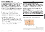
Pressure force in N
Spring travel in mm [inch]
IMG-ID: 27021598006829835
(1)
Recommended preload


