Kübler Codix 13 Series Operating Instructions Manual Download Page 8

2

1.5 Mounting instructions

1. Remove the mounting clip from the device.

2. Insert the device from the front into the panel cut-out,

ensuring the front-panel gasket is correctly seated. 

3. Slide the fixing clip from the rear onto the housing,

until the spring clamps are under tension and the

upper and lower latching lugs have snapped into

place. 

Note: In case of proper installation, IP65 can be

reached on the front side.

1.6 Electrical Installation

The device must be disconnected from any

power supply prior to any installation or main-

tenance work. Make sure that no more volt-

ages LIABLE TO CAUSE AN ELECTROCU-

TION are present. 

Signal lines carrying voltages exceeding 30V

AC or 70V DC must be operated with a

device allowing disconnecting them from the

voltage source. This device must be located

close to the equipment and marked as its dis-

connecting device – excepted when it can be

excluded that a defect presents a danger. 

Installation or maintenance work must only be

carried out by qualified personnel and in com-

pliance with the applicable national and inter-

national standards.

Take care to separate all extra-low voltages

entering or exiting the device from hazardous

electrical conductors by means of a double or

reinforced insulation (SELV circuits).

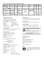
The device must be protected externally for

its proper operation. Information about the

prescribed fuses can be found in the technical

information.

• During installation, make sure that the signal inputs

are fed from the same mains phase, in order not to

exceed the maximum permitted voltage of 250V.

• The cables must be designed for the planned temper-

ature and voltage ranges. Regarding the type of the

cables, adhere to the applicable standards of the

country and of the plant. The cross sections allowed

for the screw terminals can be found in the technical

data.

• Before starting the device, check the cables for proper

wiring and tightening. The screws of unused screw

terminals must be screwed to the stop, so that they

cannot loosen and get lost.

• The device has been designed for overvoltage catego-

ry II. If higher transient voltages cannot be excluded,

additional protection measures must be taken in order

to limit the overvoltage to the values of CAT II.

1.7 Advice on noise immunity

All connections are protected against external sources

of interference. The installation location should be cho-

sen so that inductive or capacitive interference does not

affect the device or its connecting lines! Interference

(e.g. from switch-mode power supplies, motors, clocked

controllers or contactors) can be reduced by means of

appropriate cable routing and wiring. 

1.8 Measures to be taken:

• Use only shielded cable and control lines. Connect

shield at both ends.  The conductor cross-section of

the cables should be a minimum of 0.14 mm.

• The shield connection to the equipotential bonding

should be as short as possible and with a contact

area as large as possible (low-impedance). 

• Only connect the shields to the control panel, if the

latter is also earthed. 

• Install the device as far away as possible from noise-

containing cables. 

• Avoid routing signal or control cables parallel to power

lines

DC versions:

Use shielded wires for the counting and control inputs

so as to obtain the maximum EMC resistance or con-

nect not used count inputs to ground (0 V).

AC versions:

Use shielded wires for the counting and control inputs

so as to obtain the maximum EMC resistance.

1.9 Cleaning and maintenance

The front side of the unit should only be cleaned using

a soft damp (water!) cloth. Cleaning of the embedded

rear side is not planned and is the responsibility of the

service personnel or of the installer.   

In normal operation, this device is maintenance-free.

Should the device nevertheless not operate properly, it

must be sent back to the manufacturer or to the suppli-

er. Opening and repairing the device by the user is not

allowed and can adversely affect the original protection

level. 

1.10 Operation

Is the device set and programmed correctly (function;

for counters, max. counting frequency)?

!

Danger

!

Danger

Summary of Contents for Codix 13 Series

Page 1: ...cherungen abgesichert wer den Den Wert entnehmen Sie den techni schen Daten Das auf dem Ger t verwendete Symbol soll darauf hinweisen dass es Gefahren gibt auf die in dieser Anleitung hingewiesen wird...

Page 2: ...is zum Anschlag eingeschraubt werden damit sich diese nicht l sen und verlieren Das Ger t ist f r die berspannungskategorie II aus gelegt Wenn nicht ausgeschlossen werden kann dass h here transiente b...

Page 3: ...pplung INP A Z hleingang 0 INP B Z hleingang 90 Jede Flanke von INP A wird gez hlt Eingangsarten AC Count Z hl und R cksetzeingang INP A Z hleingang AC DC INP B R cksetzeingang AC DC Cnt Dir Z hleinga...

Page 4: ...t IP65 frontseitig nur Ger t Anschluss Schraubklemme RM 5 00 8 polig Nennquerschnitt max 1 x 1 5 mm2 2 x 0 75 mm2 AWG 26 14 EMV St raussendung EN55011 Klasse B St rfestigkeit EN 61000 6 2 Ger tesicher...

Page 5: ...zeingang aktiv bei negativer Flanke Kontakteingang Open Collector NPN nach 0 V DC schaltend Low Pegel 0 0 7 V DC High Pegel 3 30 V DC min Impulsdauer 50 ms Eingangswiderstand ca 2 2 MOhm Schraubklemme...

Page 6: ...schaltet Schraubklemme 5 Funktion siehe Tabelle 3 aktiv bei negativer Flanke Kontakteingang Open Collector NPN nach 0 V DC schaltend Low Pegel 0 0 7 V DC High Pegel 3 5 V DC min Impulsdauer 50 ms Eing...

Page 7: ...uses The value of these fuses can be found in the technical information This symbol is used on the device to remind of the existence of dangers which are referred to in this manual 1 3 Use according t...

Page 8: ...screw terminals must be screwed to the stop so that they cannot loosen and get lost The device has been designed for overvoltage catego ry II If higher transient voltages cannot be excluded additiona...

Page 9: ...12 8x1 Count 00 0 7 V DC NPN 07 kHz 00 0 7 V DC NPN 30 Hz 10 260 V AC DC AC DC 30 Hz Cnt Dir Up Dn Up Dn Cnt Dir Quad Quad2 NPN PNP AC DC NPN PNP 00 0 7 V DC 04 30 V DC 10 260 V AC DC 10 260 V AC DC 0...

Page 10: ...e front side Connection Screw terminals RM 5 00 8 poles Rated cross section max 1 x 1 5 mm2 2 x 0 75 mm2 AWG 26 14 EMC Interference emissions EN55011 Class B Interference resistance EN 61000 6 2 Devic...

Page 11: ...connection common for all inputs Screw terminal 7 external power supply for the LCD backlight option Screw terminal 8 external power supply for the LCD backlight option 24 V DC 20 50 mA Fuse 0 08A de...

Page 12: ...nal 5 Function see table 3 active for negative edge Contact input Open Collector NPN switching at 0 V DC Low level 0 0 7 V DC High level 3 5 V DC Min pulse duration 50 ms Input resistance ca 2 2 MOhm...

Page 13: ...enir compte du fait que seule la face avant est class e comme accessible l op rateur 1 fran ais Instructions d utilisation Compteurs affichage LCD Codix 130 131 132 133 1 Description Les compteurs aff...

Page 14: ...re viss es fond et serr es afin qu elles ne puissent pas se desserrer et se perdre L appareil a t con u pour la cat gorie de sur ten sion II Si l apparition de surtensions transitoires plus lev es ne...

Page 15: ...CA CC 6 132 012 8x3 6 133 012 8x0 6 133 012 8x1 Count 00 0 7 V CC NPN 07 kHz 00 0 7 V DC NPN 30 Hz 10 260 V CA CC CA CC 30 Hz Cnt Dir Up Dn Up Dn Cnt Dir Quad Quad2 NPN PNP CA CC NPN PNP 00 0 7 V CC 0...

Page 16: ...ion IP65 sur la face avant seulement l appareil Raccordements Bornes vis RM 5 00 8 bornes Section nominale max 1 x 1 5 mm2 2 x 0 75 mm2 AWG 26 14 CEM Emissions parasites EN55011 Classe B R sistance au...

Page 17: ...tionnant contact avec GND soustrayant 6 130 012 8x0 6 130 012 8x2 6 131 012 8x0 6 131 012 8x1 6 133 012 8x0 6 133 012 8x1 07 kHz 12 kHz 07 kHz 12 kHz 03 kHz 06 kHz NPN NPN PNP NPN PNP 30 Hz NPN NPN 07...

Page 18: ...remise z ro verrouill e Entr e en contact avec GND Touche de remise z ro d verrouill e Borne vis 5 Fonction voir le tableau 3 actif pour front n gatif Entr e de contact Open Collector NPN commutation...

Page 19: ...e protetto con fusibili esterni approvati Per i valori fare riferimento ai dati tecnici Il simbolo utilizzato sull apparecchio indica la presenza di pericoli che vengono elencati in questo manuale 1 3...

Page 20: ...zzati devono essere avvitati a fondo in modo da non perdere le viti L apparecchio stato progettato per la categoria di sovratensione II Laddove non fosse possibile esclude re la presenza di tensioni t...

Page 21: ...31 012 8x3 AC DC 6 132 012 8x3 6 133 012 8x0 6 133 012 8x1 Count 00 0 7 V DC NPN 07 kHz 00 0 7 V DC NPN 30 Hz 10 260 V AC DC AC DC 30 Hz Cnt Dir Up Dn Up Dn Cnt Dir Quad Quad2 NPN PNP AC DC NPN PNP 00...

Page 22: ...ato anteriore solo l apparecchio Collegamenti Morsetti a vite RM 5 00 8 morsetti Sezione nominale max 1 x 1 5 mm2 2 x 0 75 mm2 AWG 26 14 CEM Emissioni disturbi parassiti EN55011 Classe B Resistenza ai...

Page 23: ...one vedi Tabella 2 Morsetto a vite 6 Collegamento GND comune a tutti gli ingressi Morsetto a vite 7 alimentazione esterna per l opzione LCD retroilluminato Morsetto a vite 8 alimentazione esterna per...

Page 24: ...te negativo Ingresso di contatto Open Collector NPN commutazione a 0 V DC Livello Basso 0 0 7 V DC Livello Alto 3 5 V DC Durata d impulso min 50 ms Resistenza d ingresso circa 2 2 MOhm Ingresso Alto I...

Page 25: ...dos en las especificaciones t cnicas El s mbolo utilizado en el aparato indica los peligros a los que se hace menci n en el pre sente manual 1 3 Uso conforme a su finalidad El contador registra impuls...

Page 26: ...cados no utilizados deber n atornillarse hasta el tope para que no se suelten y se pierdan El aparato est dise ado para la categor a de sobre tensi n II Cuando no se pudiera excluir la presencia de vo...

Page 27: ...teo 0 INP B Entrada de conteo 90 Quad2 Entrada de discriminador de fase con doblado de los impulsos INP A Entrada de conteo 0 INP B Entrada de conteo 90 Se recuenta cada frente de INP A Tipo de entrad...

Page 28: ...ara frontal Conexiones Terminales de rosca RM 5 00 8 terminales Secci n nominal max 1 x 1 5 mm2 2 x 0 75 mm2 AWG 26 14 CEM Emisiones par sitas EN55011 Clase B Resistencia a par sitos EN 61000 6 2 Segu...

Page 29: ...damente 2 2 MOhm Funci n v ase Tabla 2 Terminal de rosca 6 Conexi n GND com n a todas las entradas Terminal de rosca 7 alimentaci n exterior para opci n LCD retroiluminada Terminal de rosca 8 alimenta...

Page 30: ...el terminal 4 entrada de bloqueo de la tecla de puesta a cero y el terminal 5 entrada de puesta a cero Terminal de rosca 7 alimentation exterior para la opci n retroiluminaci n Terminal de rosca 8 al...

Page 31: ...ifiques pour le retour de piles au lithium Evitez les courts circuits Pour cela prot gez les bornes de la pile l aide de ruban adh sif isolant Ne mettez pas les bornes de la pile au lithium en contact...

Page 32: ...31 012 8x0 6 133 012 8x0 BL BL INP A INP B Reset Mode GND 1 2 3 4 5 6 7 8 Reset Enable max 5 V DC max 30 V DC 24 V DC 20 50 mA max 5 V DC 10 260 10 260 VAC VDC VAC VDC BL BL INP A INP B Common AC DC G...

Page 33: ...cut out D coupe d encastrement Corte de encastre Foro d incasso 24 0 945 48 1 89 47 7 1 878 3 0 118 2 8 0 11 max 19 3 0 76 22 x 45 0 866 x 1 772 22 2 0 3 0 874 0 012 45 0 6 1 772 0 024 Panel cut out 5...

Page 34: ...R60339 0009 Index B K bler Group Fritz K bler GmbH Schubertstrasse 47 D 78054 Villingen Schwenningen Germany Phone 49 7720 3903 0 Fax 49 7720 21564 info kuebler com www kuebler com...

Reviews: