background image


KTR-STOP

®

 XS-xx-F B-xx 

Operating/Assembly instructions 

KTR-N 
Sheet: 
Edition: 

44536 EN 
1 of 25 


Please observe protection 

note ISO 16016. 

Drawn: 

2020-03-26 Shg/Wie 

Replacing: 

KTR-N dated 2017-12-19 

Verified: 

2020-03-26 Shg 

Replaced by: 


KTR-STOP

®

 XS-xx-F B-xx 


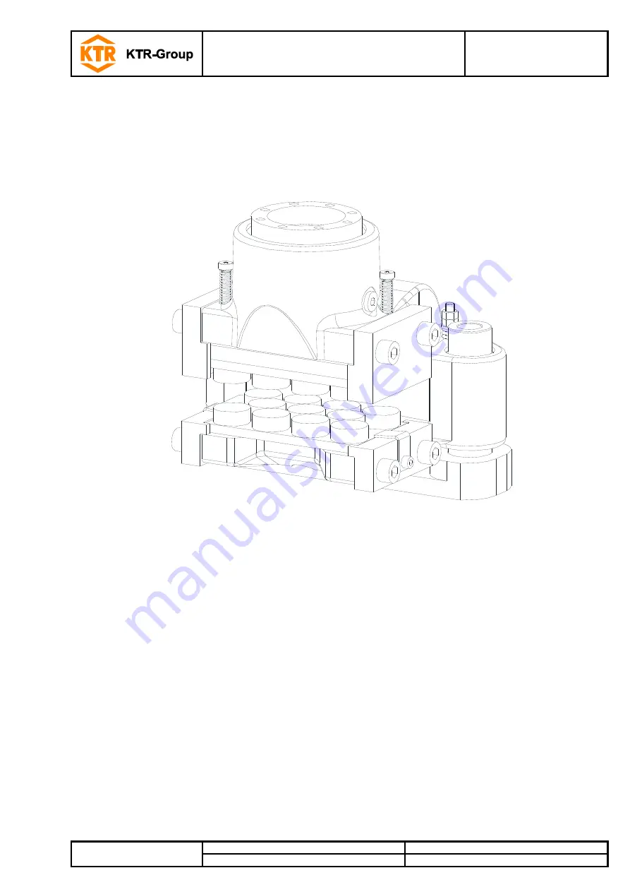
XS-xx-F B-xx is a spring-actuated brake in a floating calliper design serving to 
generate a brake force on a brake disk in order to decelerate a plant’s movement 
or stop it, respectively, or keep it at standstill. 


Summary of Contents for KTR-STOP XS F B Series

Page 1: ...016 Drawn 2020 03 26 Shg Wie Replacing KTR N dated 2017 12 19 Verified 2020 03 26 Shg Replaced by KTR STOP XS xx F B xx XS xx F B xx is a spring actuated brake in a floating calliper design serving to...

Page 2: ...orage 6 3 2 Transport and packaging 6 4 Assembly 7 4 1 Components of the brake 7 4 2 Preparation of assembly 9 4 3 Brake pads 10 4 4 Assembly of the brake 10 4 5 Setting resetting of the centering sys...

Page 3: ...of brake pad mm 70 Surface of each brake pad organic mm2 8000 Powder metal mm2 5800 Max wear of each brake pad mm 5 Rated Coefficient of friction 2 0 4 Total brake piston surface complete brake cm2 1...

Page 4: ...0 1320 1990 KTR STOP XS 8 F B xx 8 16 5 120 730 1510 2280 KTR STOP XS 9 F B xx 9 12 130 820 1700 2570 KTR STOP XS 10 F B xx 10 10 140 910 1890 2850 KTR STOP XS 11 F B xx 11 8 5 150 1000 2080 3140 KTR...

Page 5: ...instructions The operating assembly instructions are part of your product Please store them carefully The copyright for these operating assembly instructions remains with KTR STOP Warning of personal...

Page 6: ...ordance with the technical data see chapter 1 Unauthorized modifications on the brake design are not admissible We will not assume liability for any damage that may arise In the interest of further de...

Page 7: ...with guide pin 4 2 Centering system 5 2 Brake pad 6 2 Spring clamp 7 2 Cap screw DIN EN ISO 4762 12 9 8 2 Pad retraction set 9 1 2 Sensor 1 Quantity depends on thickness of brake disk 2 Optionally av...

Page 8: ...d 2020 03 26 Shg Replaced by Component assembly 3 Base plate with guide pin Component Quantity Description Illustration 6 Base plate with guide pin 3 1 1 Base plate 3 2 2 Guide pin Component assembly...

Page 9: ...the brake disk have to be inspected for dimensional accuracy For that purpose please investigate the connection dimensions connection surfaces and tolerances as specified in the drawing see illustrati...

Page 10: ...ediately Please make sure to replace by original parts only STOP In order to avoid any injuries please always make use of proper lifting equipment A thread M8 is located on the back of the brakes to f...

Page 11: ...il the balance of the screws can be assembled too see illustration 9 Screw the brake through the guide pins to the connection plate via 2 screws and tighten them evenly stepwise at the tightening torq...

Page 12: ...ntering system has to be reset regularly with wear of the brake pads For that purpose repeat the complete chapter Setting resetting of the centering system Measure the gap between the brake disk and t...

Page 13: ...ting the brake For a wash up system please make use of the pressure port on top It is not recommended to use steel plugs for venting Connect the drain line to the brake see illustration 12 and 13 For...

Page 14: ...operation of the brake is no longer ensured Illustration 14 Pressure port of several brakes in parallel Illustration 15 Pressure port of several brakes in a series The pressure port on top serves for...

Page 15: ...l of the collection container as per chapter 4 13 Put the opening pressure see table 2 on the hydraulic system to relieve the locking device for assembly The hydraulic system must never be operated at...

Page 16: ...opening pressure see table 2 on the hydraulic system to make sure that the brake pads lift off the brake disk Please note chapter 4 8 Start up of brake Screw the screw with the disk assembly lock see...

Page 17: ...he viscosity during starting should not exceed 500 mm2 s and the viscosity during operation should not fall below 12 mm2 s Filtration When filling and re filling the hydraulic system and replacing the...

Page 18: ...re the components before disassembly Remove the screw plug located at the highest point component 1 13 from the venting hole see illustrations 12 to 15 Drain the hydraulic oil completely from the brak...

Page 19: ...ke disk and brake when locking the brake in order to prevent serious injuries of your hands Before every maintenance operation please make sure that the brake is fully secured against activating Remov...

Page 20: ...on plate and remove 1 out of the 2 screws alternatively Swing the brake out of its position Please note chapter 4 4 Assembly of brake Before you reactivate the brake please observe chapter 4 8 Start u...

Page 21: ...yways in the housing are not damaged The components have to be cleaned from dirt grease and corrosion protection The components can easily be cleaned by means of solvents Afterwards dry the components...

Page 22: ...ure that the set of disk springs is mounted in the same arrangement as it was supplied If a new set of disk springs is used the condition of supply needs to be observed in detail Screw the setting nut...

Page 23: ...f the centering system Screw on the two hexagon nuts component 4 3 until they touch the disk The pressure spring needs to be pre stressed by 5 mm Counter the hexagon nut with the hexagon nut marked wi...

Page 24: ...rake locked 2 Switch position 0 unlocked 1 locked Switch S2 only shows the wear status reliably when the brake is activated locked If the brake is not activated unlocked a statement about the conditio...

Page 25: ...Max tightening torque M12 hand tight Length of cable 5 m 10 m or 15 m Material of cable PUR Dimension of cable 5 0 34 mm2 Illustration 26 Pin assignment of plug in connection Remove the screw plug com...

Reviews: